Package contents – Wayne-Dalton TORQUEMASTER 9800 User Manual
Page 3
3
Please Do Not Return This Product To The Store. Contact your local Wayne-Dalton dealer.
To find your Wayne-Dalton dealer; refer to your local yellow pages / business listings or go to Find a dealer area online at
www.wayne-dalton.com
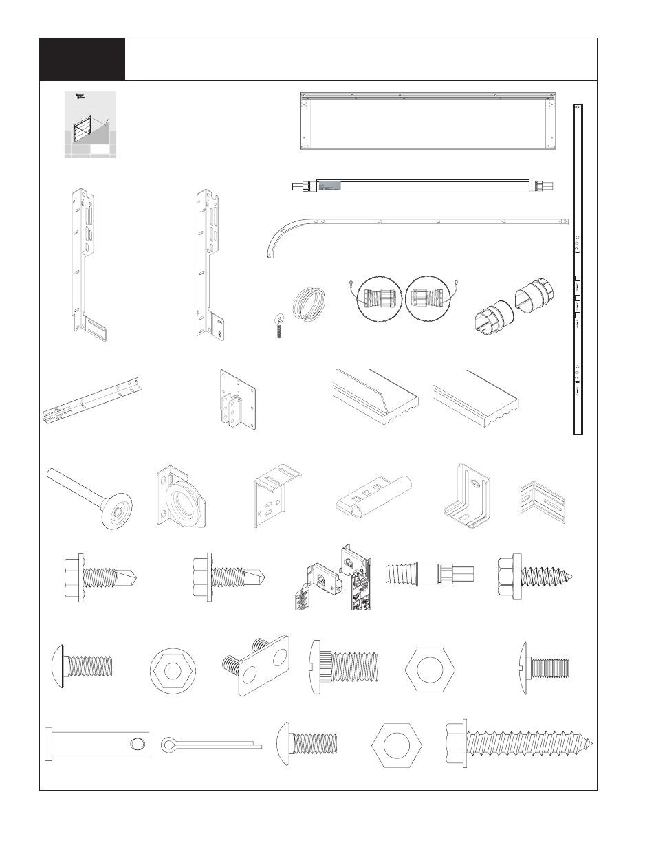
Package Contents
(1) TORquEMasTER
®
sPRING TubE
DOOR sECTIONs (as REquIRED)
(2) TOP bRaCkET slIDEs
1/4” - 14 x 5/8” sElF-TaPPING
sCREWs (as REquIRED)
1/4” - 20 x 7/8” sElF-DRIllING
sCREWs (as REquIRED)
(4) 1/4” - 20 x 5/8”
CaRRIaGE bOlTs
(2) VERTICal
TRaCks Rh/lh
(2) 3/8” - 16 x 3/4”
TRuss hEaD bOlTs
(1) CENTER bRaCkET
assEMbly
(2) quICk INsTall Rh/lh
FlaGaNGlE (as REquIRED)
(2) hORIzONTal TRaCks Rh/lh
NOTE: DEPENDING ON ThE DOOR MODEl, sOME PaRTs lIsTED WIll NOT bE suPPlIED IF NOT
NECEssaRy. REaR suPPORTs May OR May NOT bE INCluDED WITh yOuR DOOR.
ROllERs
(as REquIRED)
(1) OPERaTOR bRaCkET
(2) hORIzONTal aNGlEs
(22”, 80” OR 94”)
(as REquIRED)
(2) TOP bRaCkET basEs
sCREW EyE aND
Pull ROPE
(IF INCluDED)
5/16” x 1 5/8” hEx hEaD laG sCREWs
(as REquIRED)
(1) lOOsE WINDING shaFT
(sINGlE sPRING ONly)
RIGhT aND lEFT CablE
DRuM assEMblIEs
WEaThER sEals & NaIls
(IF INCluDED)
RIGhT & lEFT
DRuM WRaPs
TorqueMaster® Plus - Single and Double Spring
Installation Instructions and Owner’s Manual
9800 SERIES
IMPORTANT NOTICE!
Read these instructions carefully before
attempting installation. If in question about
any of the procedures, do not perform the
work. Instead, have a qualified door agency
do the installation or repairs.
© Copyright 2007 Wayne-Dalton Corp.
Part No. xxxxxx
NEW 01/03/2007
MaNual
1/4” - 20 FlaNGED hEx
NuTs (as REquIRED)
RIGhT & lEFT
END bRaCkETs
Cab
le D
rum
No
spa
ce
betw
een
Ra
tch
et
Paw
l an
d C
abl
e Dru
m
ind
ica
tes
en
gag
em
ent
Cab
le D
rum
Ratc
het
Pa
wl
EN
GA
GED
SID
E V
IEW
No
spa
ce
betw
een
Ratc
het
Paw
l an
d
Cab
le D
rum
EN
GA
GED
UN
DE
RN
EAT
H V
IEW
Spa
ce
betw
een
Ra
tch
et P
aw
l
and
Cab
le D
rum
non
-ind
ica
tes
en
gag
em
ent
Cab
le D
rum
Ratc
het
Paw
l
DIS
EN
GA
GED
SID
E V
IEW
No
spa
ce
betw
een
Ratc
het
Paw
l an
d
DIS
EN
GA
GED
UN
DE
RN
EAT
H V
IEW
UP
PER
PO
SIT
ION
LOW
ER
PO
SIT
ION
LOW
ER
PO
SIT
ION
SID
E V
IEW
UP
PER
PO
SIT
ION
SID
E V
IEW
Ratc
het
Paw
l in
Lo
we
r Po
sitio
n
Ratc
het
Pa
wl in
Up
per
Po
sitio
n
Use
the
se Ill
ust
rati
on,
in
con
jun
ction
wit
h the Instru
ctio
ns
on
the
oth
er s
ide
of
this
labe
l.
WARNING
Ra
chet B
racke
t is
under
EXT
REME
SPR
ING
TENSION
.
To avoid
possi
ble
sever
e o
r
fata
l injury
, DO NO
T remov
e
faste
ner
s from ra
tche
t brack
et
until spri
ng(
s) ar
e full
y
wnwo
und.
To sa
fely
un
win
d sp
ring(s)
rea
d
and
follo
w the dire
ctions
in the
installati
on in
structions/o
wners
manua
l.
DO NO
T RE
MO
VE
THI
S T
AG.
Ratc
het
Paw
l
EN
GA
GED
SID
E V
IEW
No
spa
ce
betw
een
ND
ER
NE
ATH
VIE
W
WA
RNING
Rachet
Brack
et is unde
r
EXT
REME
SPR
ING
TENSI
ON
.
To
avoi
d possi
ble
sever
e or
fatal inju
ry, DO NO
T remov
e
fas
teners f
rom
ratche
t brack
et
unti
l sp
ring(s
) are
fully
wnwo
und.
To safely un
win
d spring
(s)
rea
d
and fo
llow
the di
recti
ons
in the
instal
lati
on inst
ruc
tions/
ow
ner
s
manu
al.
DO NO
T RE
MOV
E T
HIS T
AG.
q.I. jaMb bRaCkETs
(as REquIRED)
(2) 3/8” - 16 hEx
NuTs
(1) COTTER PIN
(1) 5/16” x 1-1/4”
ClEVIs PIN
(2) 5/16” - 18 x 3/4”
CaRRIaGE bOlTs
(2) 5/16” - 18
hEx NuTs
(2) Fully aDjusTablE Rh/lh
FlaGaNGlE (as REquIRED)
sTuD PlaTEs
(as REquIRED)
1/4” - 20 x 5/8” sElF-DRIllING
sCREWs (as REquIRED)
F.a. jaMb bRaCkETs
(as REquIRED)
DOOR sTOP & NaIls
(IF INCluDED)
1/4” - 20 x 9/16” laRGE
hEaD RIbbED TRaCk bOlTs
(as REquIRED)