Inst alla tion inst alla tion, Cable drums continued, End brackets – Wayne-Dalton TORQUEMASTER 9800 User Manual
Page 23: 23 tools needed: tools needed, Spring tube assembly, Groove cable drum splines winding shaft, Loose winding shaft
23
Tools Needed:
Tools Needed:
Please Do Not Return This Product To The Store. Contact your local Wayne-Dalton dealer.
To find your Wayne-Dalton dealer; refer to your local yellow pages / business listings or go to Find a dealer area online at
www.wayne-dalton.com
INST
ALLA
TION
INST
ALLA
TION
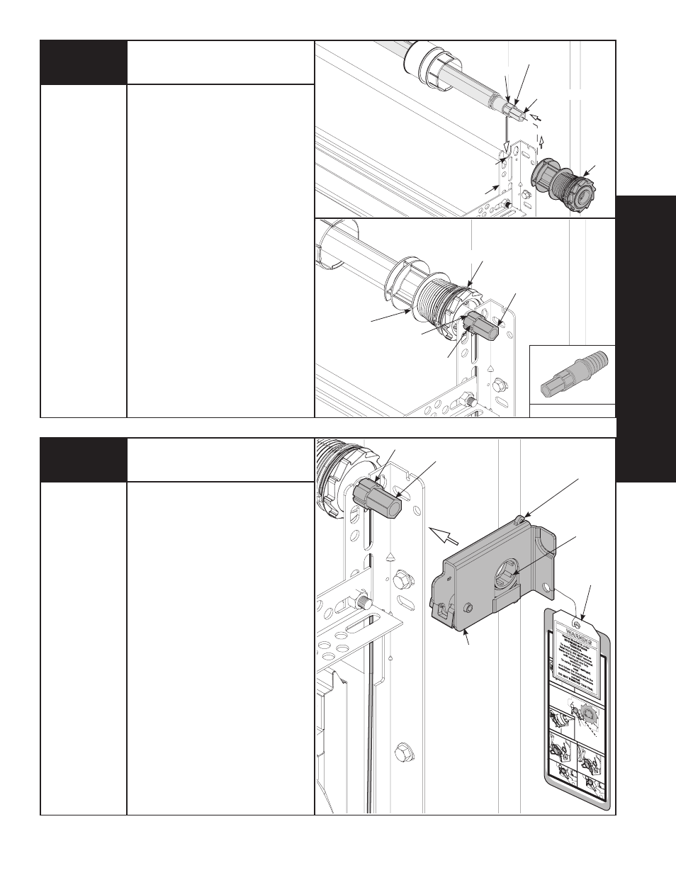
The winding shaft must extend past the
cable drum far enough to expose the
splines and the groove. align the winding
shaft groove with the round notch in the
flagangle.
for double spring applications:
Repeat for opposite side.
for single spring applications: Insert
the loose winding shaft into the left
hand cable drum prior to sliding the
cable drum over the TorqueMaster
®
spring tube assembly.
NOTE: On single spring applications,
take care in handling the loose winding
shaft (left side) so that it does not slide
back into the TorqueMaster
®
spring tube
assembly.
WINDING shaFT
CablE
DRuM
GROOVE
ROuND NOTCh
FlaGaNGlE
sPlINEs
COuNTERbalaNCE CablE
Cable Drums Continued...
lOOsE WINDING shaFT
GROOVE
CablE
DRuM
sPlINEs
WINDING shaFT
Cable Dr
um
No space bet
ween Ratc
het
Pawl and
Cable Dru
m
indicates enga
gement
Cable
Drum
Ratc
het Paw
l
ENGAGED
SID
E VIEW
No space b
etween
Ratchet Pawl
and
Cable Dru
m
ENGA
GED
UND
ERNE
ATH
VIEW
Space
betwee
n Ratchet
Pawl
and Ca
ble Drum
non-
indicates
engagem
ent
Cable Dru
m
Ratc
het Paw
l
DISE
NGAGED
SIDE VIEW
No space
between
Ratchet Paw
l and
DISE
NGAGED
UNDER
NEATH
VIEW
UPPER
POSI
TION
LOWER
POSITI
ON
LOWER P
OSI
TION SI
DE VI
EW
UPPER P
OSI
TION
SIDE V
IEW
Ratchet Paw
l in Lo
wer
Position
Ratc
het Pawl
in Up
per Position
Use
these
Illu
strat
ion, in
conj
unctio
n with th
e In
struc
tions on
the othe
r side
of
this labe
l.
WARNIN
G
Rach
et Bra
cket is
unde
r
EXTR
EME
SPR
ING
TENS
ION.
To av
oid p
ossib
le sev
ere o
r
fatal in
jury, D
O NO
T re
move
faste
ners fro
m ra
tchet
brack
et
until s
pring
(s) are
fully
wnw
ound
.
To sa
fely u
nwin
d sprin
g(s)
read
and fo
llow
the d
irectio
ns in th
e
installa
tion in
stru
ctions/
owne
rs
manu
al.
DO N
OT R
EMO
VE T
HIS T
AG.
IMPORTANT: WaRNING TaGs MusT bE
sECuREly aTTaChED TO bOTh END
bRaCkETs.
End brackets are right and left hand. you
can identify the right hand end bracket
by the disconnect cable guide hole in
the top of the bracket.
beginning with either side, slide the end
bracket onto the winding shaft so that
the grooves in the ratchet wheel fit onto
the winding shaft splines.
sPlINEs
WINDING
shaFT
GROOVE
DIsCONNECT
CablE GuIDE
hOlE
RIGhT END
bRaCkET
WaRNING
TaG
20
End Brackets
Power Drill
7/16” socket
Driver
9/16” Wrench