Multi-room system connections, Connection diagram, Main room sub-room – Onkyo TX-DS656 User Manual
Page 47
47
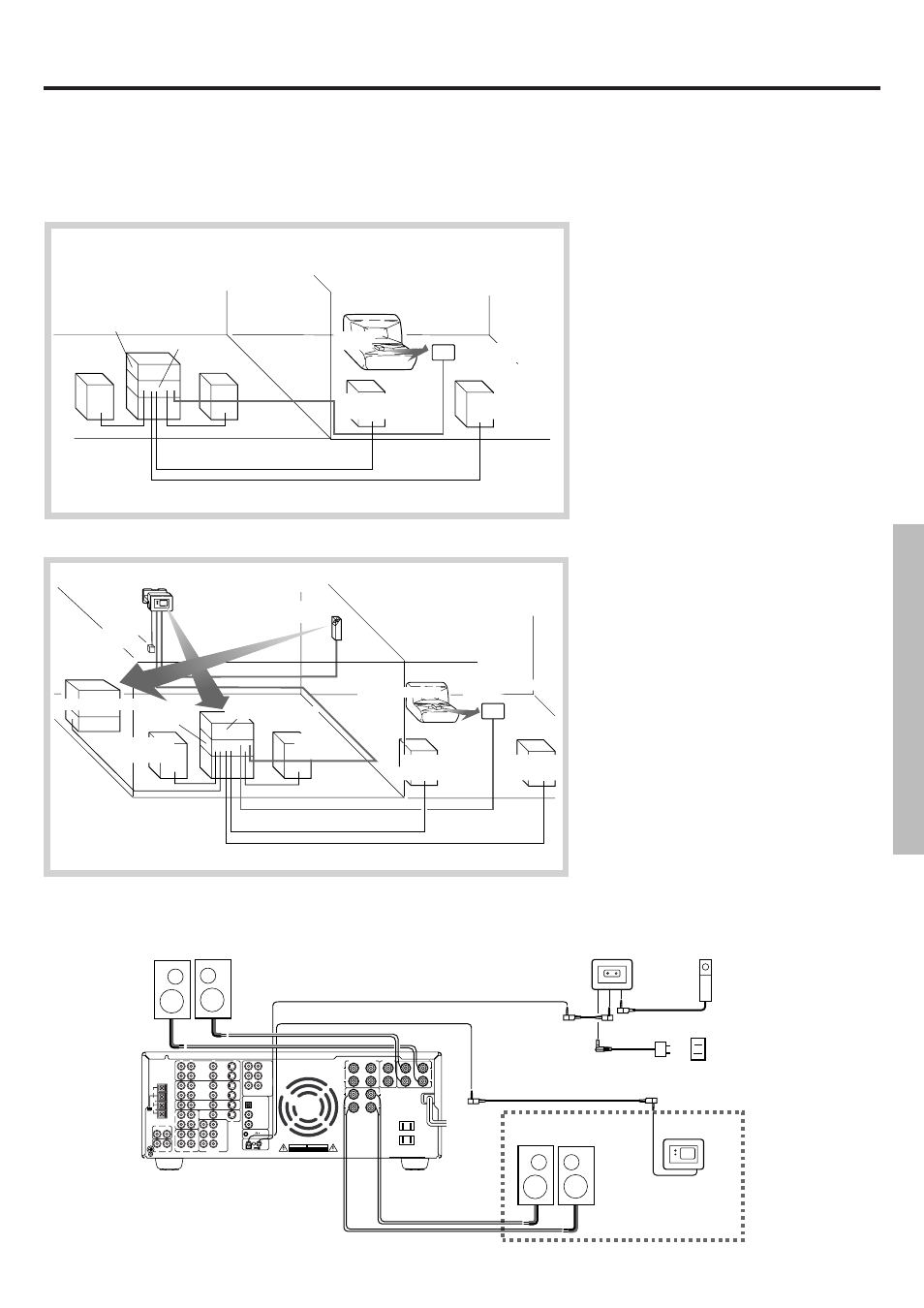
MAIN ROOM
SUB-ROOM
Remote sensor
HR-10
5. Remote Emitter
Head HE-10
Power
supply
3. Remote Emitter
HE-50(AC)
TX-DS656
4. Components(c)
Main
speaker
Main
speaker
1. Components(b)
Remote
speaker
Remote control
Remote
speaker
Multi-room system connections
Models other than U.S.A. and Canadian models (Onkyo Multi-Room Systems)
Do not plug in the power cord until all connections have been made.
When making connections 1 through 4, be sure to connect the units as shown in the connection diagram below. Do not make a mistake when
connecting the units.
A. Operating components displaying Onkyo's z mark from the sub-room
Components mounted in a rack should be connected as shown below to enable remote control operation.
1. Set up the components (a) displaying
Onkyo's z mark.
2. Connect the sub-room speaker cables to the
FRONT REMOTE SPEAKERS connectors
on the TX-DS656. (1)
3. Install Remote Sensor HR-10 in the sub-
room, then connect it to the TX-DS656. (2)
B. Using a remote controller to operate components not displaying Onkyo's z mark from the sub-room
1. Connect the components (b) to the TX-DS656.
2. Make the connections described above in
steps 2 through 3 of section A.
3. Install Remote Emitter HE-50 (AC) so that
its sensor is directed toward these compo-
nents, then connect it to the TX-DS656. (3)
(Connect the AC adapter to the Remote
Emitter.)
■ Operating components which are positioned
out of the range of the emitter installed as
described above.
4. Connect the components (c) to the TX-DS656.
5. Install Remote Emitter Head HE-10 so that
its sensor is directed toward these
components, then connect it to the HE-50
(AC). (4)
MAIN ROOM
SUB-ROOM
3. Remote sensor
HR-10
Remote
control
TX-DS656
1. Onkyo components (a)
Main
speaker
Main
speaker
2. Remote
speaker
2. Remote
speaker
Connection diagram
MJ
27122482
ANTENNA
AM
R
V
L
OUT
IN
VIDEO-1
OUT
IN
VIDEO-2
OUT
IN
OUT
IN
IN
IN
TAPE-1
TAPE-2
DVD
OUT
IN
OUT
R
L
R
L
PHONO
CD
GND
(PLAY)
(REC)
(PLAY)
(REC)
R
L
CENTER SUBWOOFER
SURROUND
FRONT
R
L
R
L
V
PRE OUT
FRONT
R
L
R
L
DIGITAL INPUT
DIGITAL 1
(OPTICAL)
DIGITAL 2
(COAXIAL)
OUT
IN
REMOTE CONTROL
R
L
AC OUTLETS
MONITOR
OUTPUT
SURROUND
CENTER
SUBWOOFER
DIGITAL 3
(COAXIAL)
S
MULTI
CHANNEL
INPUT
L
R
R
L
S
IN
SURROUND SPEAKERS
FRONT
SPEAKERS
MAIN
CENTER
SPEAKER
AC 120V 60Hz
SWITCHED
TOTAL 120W 1A MAX.
FRONT REMOTE SPEAKERS
FM
75
FM
300
WARNING
RISK OF ELECTRIC SHOCK
DO NOT OPEN
RISQUE DE CHOC ELECTRIQUE
NE PAS OUVRIR
AVIS
CAUTION: SPEAKER IMPEDANCE
6 OHMS MIN. / SPEAKER
1
4
3
2
TX-DS656
MAIN Speaker (Main Room)
Remote Emitter
AC adapter
REMOTE Speaker
(Sub-room)
Remote Sensor
SUB-ROOM