Interconnection cable wiring method, Null modem cable pinouts, Mating face of 25d female connector – Network Technologies CAT5 User Manual
Page 52: Mating face of 9d male connector
47
INTERCONNECTION CABLE WIRING METHOD
The CAT5 connection cable between the remote and local is terminated with RJ45 connectors and must be wired according to the
EIA/TIA 568 B industry standard. Wiring is as per the table and drawing below.
Pin
Wire Color
Pair
Function
1
White/Orange
2
T
2
Orange
2
R
3
White/Green
3
T
4
Blue 1
R
5
White/Blue
1
T
6
Green 3
R
7
White/Brown
4
T
8
Brown 4
R
SH
Drain
wire
-
Shield
Figure 46- View looking into RJ45 female
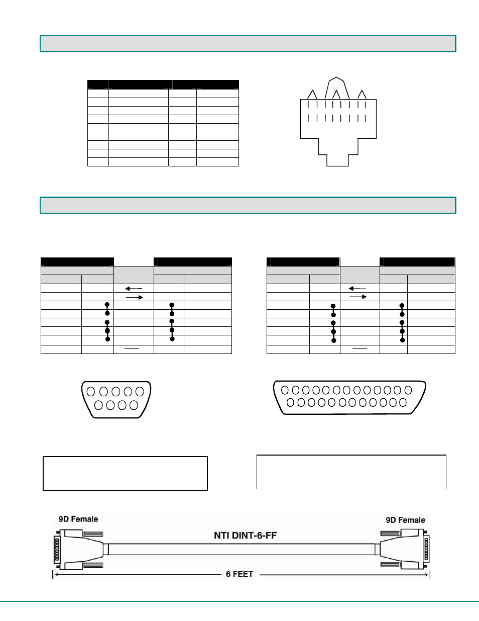
NULL MODEM CABLE PINOUTS
An NTI DINT-6-FF 6 foot null modem cable has been supplied to make connection between your PC terminal and the PRIMUX in
order to perform firmware upgrades or save and restore configuration files. The pinouts for this cable are detailed below should
you wish to make a longer cable (not to exceed 15 feet).
PRIMUX to Terminal (9 PIN) null modem cable
PRIMUX to Terminal (25 PIN) null modem cable
PRIMUX
TERIMINAL
PRIMUX
TERMINAL
9 pin
Signal
9 pin
9 pin
Signal
25 pin
Function
Pin #
Direction
Pin #
Function
Function
Pin #
Direction
Pin #
Function
RxD
2
3
TxD RxD
2
2
TxD
TxD 3
2 RxD
TxD 3
3
RxD
CTS 8
N/C
7 RTS
CTS 8
N/C
4
RTS
RTS 7
N/C
8 CTS
RTS 7
N/C
5
CTS
DSR 6
N/C
4 DTR
DSR 6
N/C
20
DTR
DTR 4
N/C
6 DSR
DTR 4
N/C
6 DSR
DCD 1
N/C
1 DCD
DCD 1
N/C
8 DCD
SG 5
5
SG
SG 5
7
SG
N/C= not connected (no cable wire)
In this cable signals CTS and RTS are connected to each other at the connector ends, and
signals DSR, DTR, and DCD are connected to each other at the connector ends.
Note: Cable length not to exceed 15ft.
T
1
+
R
2
-
T
3
+
R
4
-
T
5
+
R
6
-
T
7
+
R
8
-
Pair 2
Pair 1
Pair 4
Pair 3
Mating Face
of 25D
Female Connector
1
14
25
13
1
Mating Face
of 9D
Male Connector
2
3
4
5
6
7
8
9
NTI Parts to make:
DB25F-SLDR + DB9F-SLDR + DB25-HOOD-SHLD +
Any 20-24AWG 3-wire cable
NTI Parts to make:
DB9F-SLDR (X2) + DB9-HOOD-SHLD (X2) +
Any 20-24AWG 3-wire cable