999a – Lakeshore Learning Materials 622 User Manual
Page 86
Lake Shore Model 620/622/623/647 Magnet Power Supply User’s Manual
Mainframe Control Bus Operation
B-2
B4.0 CONTROL BUS SERIAL INTERFACE CONFIGURATION
Configure the control bus serial interface for either RS-232C or RS-485 communications with DIP switches on
the Communications Processor Board (CMP). The CMP plugs into the Mainframe rear panel. The standard
control bus serial interface configuration is RS-485. Use the procedure below to change or verify the serial
interface configuration.
1. Turn off Mainframe and unplug the power cord.
2. Loosen the two screws that secure the CMP to
the rear panel and slide the CMP out.
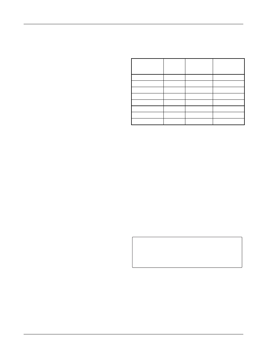
3. Locate and configure the control bus serial
interface DIP switches as defined in the table to
the right. The DIP switches are just inside the
CMP front panel. Switches 1-4 define the
interface as RS-232C. Switches 5-8 define the
interface as RS-485 multidrop. Switch 8
activates 100
Ω
bus termination for long serial
interface runs. For RS-485, terminate extremely
long main lines at the furthest point from the
host. Limit main line length to under 4000 feet
and multiple short stub lines from the main line
(Mainframe to Mainframe) to under 50 feet. A typical RS-485 configuration runs the main line from the
host to one of the first Mainframe serial interface jacks; a Model 2001 cable plugs into the other first
Mainframe serial interface jack to connect to the second Mainframe, and so on. Connect up to 32
Mainframes in this way. Terminate the last Mainframe only if it is a significant distance from the host.
Assign unique addresses to multiple Mainframes on a RS-485 interface.
4. Replace the CMP.
B5.0 SELECTING THE CONTROL BUS SERIAL INTERFACE ADDRESS
Multiple Mainframes on the RS-485 interface each have a unique address and operate in a polled mode. Set
the MPS Mainframe to respond to one of 32 addresses. Prefix all commands sent to a Mainframe with the
Mainframe address. A Mainframe query response includes the address prefix if the address is not 0. The
receipt of the LF (0AH) terminator resynchronizes communications and alerts all Mainframes that the next
character is an address. A Mainframe with address 0 responds to all commands on the interface. A Mainframe
using RS-232C can be given a unique address as well, but RS-232C is not suited for multi-drop operation.
Access the Control Bus serial interface address from the Interface Setup screen. Press the Function Menu
key to display Function Menu 1. Press the key corresponding to INTERFACE SETUP to display the Interface
Setup screen.
Use the cursor key to move to the line indicating CB DEF and CB ADD; defined as follows.
CB DEF: 9600 Baud, No Parity, 8 Data Bits, and 1
Stop Bit
Control Bus Definition. The control bus should be
defined as above.
CB ADD: 0 to 32
Control Bus Address. Use the Data Entry up or
down arrows to increment or decrement the Control Bus Address. The initial condition is 0.
CMP
Configuration
DIP Switch
RS-232C Terminated
RS-485
Unterminated
RS-485
1 Closed
Open Open
2 Closed
Open Open
3 Closed
Open Open
4 Closed
Open Open
5 Open
Closed
Closed
6 Open
Closed
Closed
7 Open
Closed
Closed
8 Open
Closed
Open
I N T E R F A C E S E T U P :
¤ I E E E A D D
T R M S / E O I
R S 2 3 2 C
C B D E F
C B A D D
V W A N G L E
M F I D
O U T P U T S :
*
+1.999A
: 1 2
: (CR LF) EOI
: 9 6 0 0 , N , 8 , 1
: 9 6 0 0 , 0 , 7 , 1
: 0
: 9
: 6 2 2 ( 1 )
¥
¥
¥
¥
¥
+ 0 . 0 0 1 V