Lakeshore Learning Materials 622 User Manual
Page 15
Lake Shore Model 620/622/623/647 Magnet Power Supply User’s Manual
Introduction
1-5
Conventional MPS: Consists of a unipolar power supply with an energy absorber to dissipate magnet energy
during discharge. The energy absorber prevents reverse voltage generated during the discharge from
damaging the unipolar supply output. Other conventional supplies dissipate magnet energy in the power
supply output transistor pass-bank. This two-quadrant performance requires the output stage to absorb
considerable power during the discharge. In addition, uniform charge and discharge rates are not always
ensured.
Current reversal requires external current reversal switches or manual lead reversal. These units provide
pseudo-four-quadrant operation which introduces discontinuities at the current reversal point produced by
switching the leads. Current reversal switches may incorporate direction detection diodes which reduce
available magnet charging voltage and dissipate additional power. Current reversal switches must also
interlock to prevent lead reversal when current is present. Current reversal switches complicate high power
cabling requirements, increase chances of introducing output current instabilities, and require time to reverse
leads. Manual lead reversal introduces discontinuity at the current reversal point. A discontinuous transition
through zero current may require a small external supply for near zero current analysis. Utility power failure in
a conventional supply generally results in a magnet quench.
1.3.2
Low Noise, High Stability Current Regulated Output
Lake Shore MPS: Maintains a high-stability,
low-noise, current-regulated output. Digital
setting and monitoring electronics, and
computer interfacing integrate into power
management and precision analog control
circuitry. This integration maintains high output
stability and repeatability. Extensive output
filtering and noise cancellation circuitry keep
MPS output noise very low. The MPS front
panel graphic display allows continuous display
of output current and voltage while setting
parameters from the menu-driven keypad. In
addition to the front panel and remote interface
programming, the MPS includes analog inputs
and outputs for setting and monitoring operating
parameters. The MPS requires only 7 inches of
rack space.
Conventional MPS: Some use a compliance
limited output with current monitoring to charge
the magnet. Others require output current to
drive against the output current limit to prevent
output current drift. Most use multi-turn
potentiometers and digital (or analog) panel
meters for front panel current and compliance
voltage setting. The elegance and repeatability of keypad entry is not available. There is no digital setting or
monitoring integration in the output control circuitry. Most achieve computer interfacing by adding computer
controlled voltage sources to analog program the output current and voltage. Additional inputs must be
added to digitize the output current and voltage. Setting and monitoring resolution is one to two orders of
magnitude poorer than the standard MPS provides. External setting and monitoring complicates cabling.
Degradation of the output current stability due to the addition of external cabling is undefined. Output noise
specifications are rarely given and sometimes vary with the type of magnet load driven. These multiple unit
configurations require up to 36 inches of rack space.
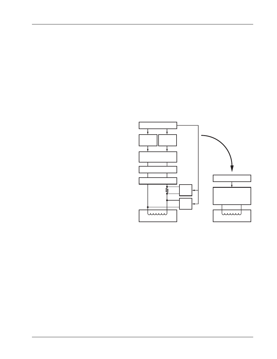
Magnet Load
Analog
Current
Programmer
Analog Programmed
Power Supply
Current Reversal
Energy Absorber
Analog
Voltage
Programmer
Computer
DVM
Current
Monitor
DVM
Voltage
Monitor
Magnet Load
Lake Shore MPS
True, Four-Quadrant
Bi-Directional
Power Flow
Computer
Now
Replaced
by:
Figure 1-2. Comparison of Old and New MPS Designs