999a – Lakeshore Learning Materials 622 User Manual
Page 31
Lake Shore Model 620/622/623/647 Magnet Power Supply User’s Manual
Operation
3-5
3.6 FUNCTION
MENUS
The MPS uses a system of three Function Menus for setup. Function Menus 1 and 2 do not require a PSH
Option Card, but the presence of one changes the look of the menus. The Function Menu 3 requires a PSH
Option Card in order to display. Press Function Menu to display Function Menu 1. To choose a different
menu, press Next Menu; Function Menu 2 displays. Each press of Next Menu displays the next menu.
Pressing Next Menu with Function Menu 3 displayed returns to Function Menu 1. To exit a Function Menu,
press Function Menu. To exit the menu system, press Normal Display or Escape. See Figure 3-1.
3.6.1
Function Menu 1
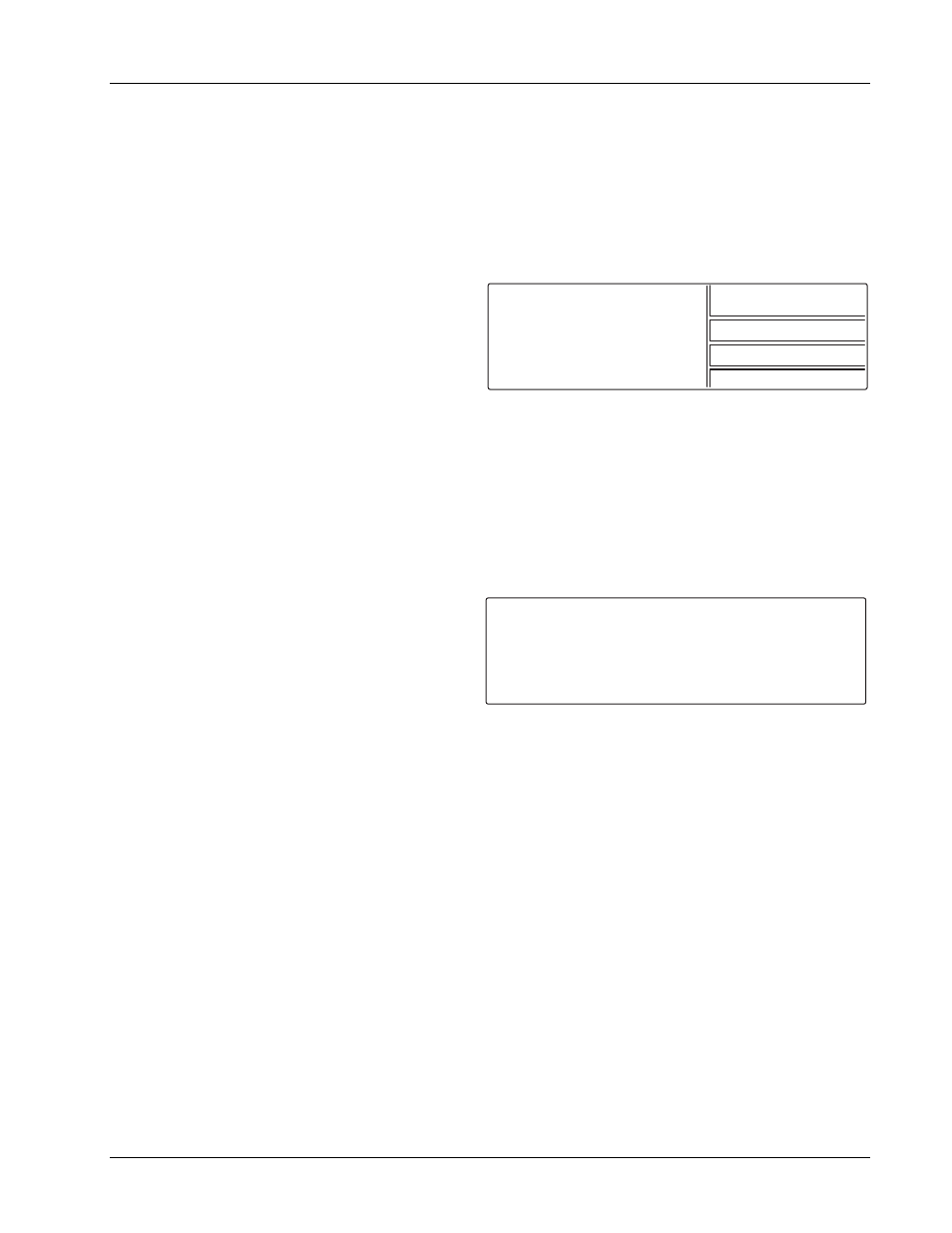
Function Menu 1 for an MPS with a PSH Option
Card appears to the right. The 1/3 in the upper right
corner indicates Menu 1 of 3. It has four selections:
AUTOMATIC MODE/MANUAL MODE, INTERFACE
SETUP, STEP LIMIT/ZERO and INSTR. SETUP.
3.6.1.1
Automatic Mode / Manual Mode
AUTOMATIC MODE appears in the menu only on MPS units with a PSH Option Card installed and operating
in MANUAL MODE. Without a PSH Option Card, this menu item is empty and a “1/2” appears in the upper
right corner indicating menu 1 of 2. If the PSH option is installed, then the menu item toggles between
MANUAL and AUTOMATIC PSH control. If the unit is in MANUAL MODE this menu item reads AUTOMATIC
MODE and pressing the corresponding Display Function key places the MPS in AUTOMATIC PSH control
mode. If the unit is in AUTOMATIC MODE, this menu item reads MANUAL MODE and pressing the
corresponding Display Function key places the MPS in MANUAL PSH control mode.
3.6.1.2
Interface Setup Screen
Press the Function Menu key followed by the
INTERFACE SETUP Function key to display setup
screen to the right. Use the Cursor keys to move the
line indicator up or down. Parameters with a ¥ icon
change with the Data Entry up or down key. Change
all others using any numeric entry mode, including
the cursor.
IEEE ADD:
1 to 30
Defines the IEEE Address. The default is 12.
TRMS/EOI:
CR LF, LF CR, DAB, LF, with or without EOI
Choose from the following options: (CR LF) EOI, (LF CR) EOI, (DAB) EOI, (LF) EOI, (CR LF), (LF CR), (DAB),
(LF). When EOI displays, End Or Identify (EOI) is asserted during the last byte of a multibyte transfer. The
default is Carriage Return and Line Feed (CR LF) with EOI ON.
RS-232C: 1200,N,8,1
Select 300, 1200, or 9600 Baud. The other parameters are fixed at No Parity, 8 Data Bits, and 1 Stop Bit.
CB DEF:
9600,o,7,1 (Read only)
Control Bus Definition. Fixed at 9600 Baud, odd parity, 7 data bits, and 1 stop bit. See Appendix C.
CB ADD:
0 to 32
Control Bus Address. See Appendix C.
VW ANGLE:
2 to 9
Display viewing angle. 9 indicates viewing from above, 5 in the middle, and 2 from below. Initial value is 5.
MF ID:
620 (1), 622 (1), 623 (1), or 647 (1) (Read only)
MPS ID. A 1 indicates only one MPS. On the master MPS (MPS1) of a multiple MPS configuration, the number
indicates the number of units connected in parallel. A slave MPS with a display in a multiple MPS configuration
displays “S” (for slave) instead of a number. Polling at power up determines the number of units in parallel.
1/3
AUTOMATIC MODE
INTERFACE SETUP
STEP LIMIT/ZERO
INSTR. SETUP
I N T E R F A C E S E T U P :
¤ I E E E A D D
T R M S / E O I
R S 2 3 2 C
C B D E F
C B A D D
V W A N G L E
M F I D
O U T P U T S :
*
+1.999A
: 1 2
: (CR LF) EOI
: 9 6 0 0 , N , 8 , 1
: 9 6 0 0 , 0 , 7 , 1
: 0
: 9
: 6 2 2 ( 1 )
¥
¥
¥
¥
¥
+ 0 . 0 0 1 V