Appendix b, Mainframe control bus operation – Lakeshore Learning Materials 622 User Manual
Page 85
Lake Shore Model 620/622/623/647 Magnet Power Supply User’s Manual
Mainframe Control Bus Operation
B-1
APPENDIX B
MAINFRAME CONTROL BUS OPERATION
B1.0 GENERAL
There are seven elements to the Model 622/623 Mainframe Control Bus operating instructions: Control Bus
Serial Interface Specifications (Paragraph B2.0), Control Bus Serial Interface Connector (Paragraph B3.0),
Control Bus Serial Interface Configuration (Paragraph B4.0), Selecting the Control Bus Serial Interface
Address (Paragraph B5.0), Control Bus Serial Interface Operation (Paragraph B6.0), and a sample control bus
serial interface program (Paragraph B7.0).
B2.0 CONTROL BUS SERIAL
INTERFACE SPECIFICATIONS
The MPS Mainframe control bus serial
interface may be configured either for
RS-232C or RS-485. RS-232C is an
unbalanced (single ended), non
terminated line for short distances
(typically less than 50 feet) where the
host computer serial interface is
dedicated to one MPS Mainframe.
RS-485 is a balanced, terminated line
for multidrop (party-line)
configurations with up to 32 drivers
and receivers sharing the same line
for data transmission. Each interface
instrument has a unique address and
operates in a polled mode. Set the
MPS Mainframe to respond to one of
32 addresses.
B3.0 CONTROL BUS SERIAL INTERFACE CONNECTOR
The serial interface connectors use dual standard
6-wire RJ-11 modular (phone) jacks. The two
connectors are in parallel and facilitate the RS-485
multidrop configuration. Lake Shore Model 2001 data
cables, which maintain pin 1 polarity, simplify multiple
Mainframe interconnection. Lake Shore offers the
Model 2002 RJ-11 to DB-25 adapter and Model 2003
RJ-11 to DE-9 adapter to connect to the host
computer.
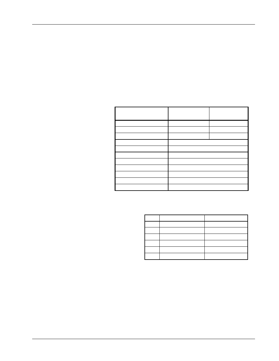
Serial Interface
Specification
Configured
For RS-232C
Configured
For RS-485
Transmission
Three Wire
Two Wire
Address Configuration
None
Polled 1-32
Distance
50 Feet
4000 Feet
Connector
Dual RJ-11 Modular (phone) Jacks
Timing Format
Asynchronous
Transmission Rate
Half Duplex
Baud Rate
9600
Bits per Character
1 Start, 7 Data, 1 Parity, 1 Stop
Parity Type
Odd
Data Interface Levels
Tx/Rx Using EIA Levels
Terminator LF
(0AH)
Pin
RS-232C Function
RS-485 Function
1
No Connection
No Connection
2 Receive
Data
A
3
Signal Ground
No Connection
4
Signal Ground
No Connection
5 Transmit
Data
B
6
No Connection
No Connection