999a, 000a – Lakeshore Learning Materials 622 User Manual
Page 73
Lake Shore Model 620/622/623/647 Magnet Power Supply User’s Manual
Options & Accessories
6-5
6.2.5.2
Field Probe Setting and Calibration
Press Function Menu and then Next Menu to
display Function Menu 2. Press the FIELD Function
key to display the Field screen to the right.
FIELD PROBE SETTING:
UNITS: T or kG
Field Units. The Data Entry up or down arrows scroll
between the units: T (tesla) or kG (kilogauss). The default is kG.
CALIBRATE PROBE:
NOTE: The entries below change probe calibration. Do not change unless probe is actually being calibrated.
mV/kG: +XXX.XXX
Field Probe Sensitivity. Each Hall Probe comes with a mV/kG sensitivity. Use any numeric entry mode to
change the value from 0 to 999.999.
ZERO RDG:
Field Probe Zero Reading. Connect the Hall Probe and place it in zero magnetic field. Press a Data Entry up
or down arrow key to zero the probe.
6.2.6
Level Sensor Calibration
To enter or measure level sensor parameters,
select CALIBRATE SENSOR (line 8) in the LIQUID
HELIUM LEVEL screen. Prior to this, select a length
of inches or centimeters (not percent). Units of
length do not display on the calibration screen if
percent is selected.
LENGTH: 24.0 in or LENGTH: 61.0 cm
Level Sensor Length. Use any numeric entry mode to change the value. Allows values from 0.0 to 999.9.
MIN
Ω
Ω
Ω
Ω
: 0.00 (ohms)
Level Sensor minimum resistance in ohms. If minimum resistance is known, enter it directly with the Data
Entry keys. Otherwise, measure it as shown below under SELF CALIBRATION: CALIBRATE MIN
Ω
Ω
Ω
Ω
.
Ω
Ω
Ω
Ω
/inch: 10.41 or
Ω
Ω
Ω
Ω
/cm : 4.10
Level Sensor resistance per unit length. If the value is known, enter it directly with the Data Entry keys.
Otherwise, it can be measured as shown below under SELF CALIBRATION: CALIBRATE
Ω
/inch(cm).
CALIBRATE MIN
Ω
Ω
Ω
Ω
¥
¥
¥
¥
Measures the Level Sensor minimum resistance. Connect the level sensor immersed in LHe to the active level
sensor length. Move the cursor to CALIBRATE MIN
Ω
Ω
Ω
Ω
and press a Data Entry up/down arrow key. That line of
the display changes to CALIBRATING MIN
Ω
Ω
Ω
Ω
…. After measurement, the display updates the minimum
resistance in line 3 and the display returns to that shown above.
CALIBRATE
Ω
Ω
Ω
Ω
/inch ¥
¥
¥
¥
or CALIBRATE
Ω
Ω
Ω
Ω
/cm ¥
¥
¥
¥
Measures the Level Sensor resistance per unit length. The resistance per unit length is a function of
temperature. The effective value can be determined from the value measured at a more convenient
temperature. Figure 6-1 and Table 6-2 show the resistance values as a function of temperature of a NbTi
filament. The procedure described below measures the resistance per unit length at room temperature.
Take the level sensor out of the liquid and allow its temperature to stabilize. Move the cursor to CALIBRATE
Ω
Ω
Ω
Ω
/inch and press a Data Entry up/down arrow key. That line of the display changes to CALIBRATING
Ω
Ω
Ω
Ω
/inch(cm)…. After measurement, the display updates the
Ω
/inch (
Ω
/cm) in line 4 and the display returns to
that shown above.
NOTE: If the resistance is too large, the value is not updated. In that case, use a lower temperature or an
ohmmeter to measure the resistance.
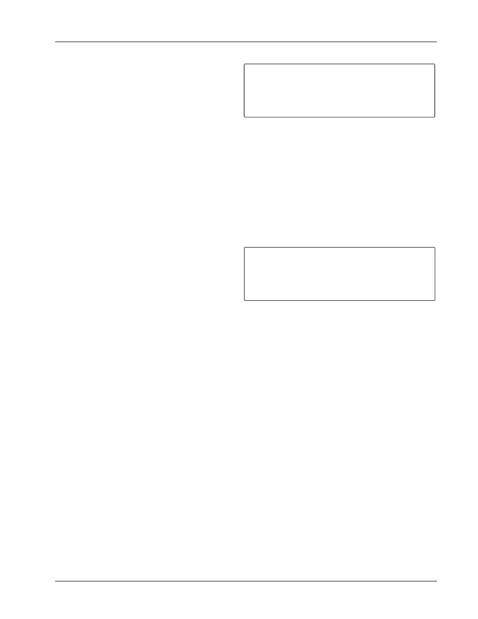
F I E L D P R O B E S E T T I N G :
¤ U N I T S
C A L I B R A T E P R O B E
m V / k G
Z E R O R D G
O U T P U T S :
*
+1.999A
: k G ¥
: + 0 . 8 0 0
: ¥ T O C A L I B R A T E
L V L : + 1 4 . 4 i n
F L D : + 0 . 5 0 1 k G
+ 0 . 0 0 1 V
L E V E L S E N S O R C O N S T A N T S :
¤ L E N G T H
M I N ¦
¦ / i n c h
S E L F C A L I B R A T I O N :
C A L I B R A T E M I N ¦
C A L I B R A T E ¦ / i n c h
O U T P U T S :
*
+0.000A
: 2 4 . 0 i n
: 0 . 0 0
: 1 0 . 4 1
L V L : + 1 4 . 4 i n
F L D : + 0 . 5 0 1 k G
+0.000V
¥
¥