Load mps #1 rear view mps #2 rear view, Setup & connections – Lakeshore Learning Materials 622 User Manual
Page 24
Lake Shore Model 620/622/623/647 Magnet Power Supply User’s Manual
Setup & Connections
2-8
1
2
3
4
5
6
7
8
9
10 11 12 13 14 15 16 17 18
+
-
+
-
+
-
OVP Im Vm m Vp +Vs -ls lp +ls -S +S
CAL AND ID
V
l
MODE
INT
V
l
EXT
RI
FLT
ON
WARNING:
NO USER SERVICEABLE PARTS INSIDE. REFER
SERVICING TO TRAINED SERVICE PERSONNEL.
208
220
240
100
120
-10% +5% 50-60 Hz
FIXED INTERNALLY
LINE
N
L
!
-OUT
+OUT
10K
10K
+
-
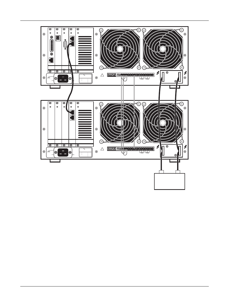
LOAD
MPS #1 Rear View
MPS #2 Rear View
Figure 2-4. Typical Multiple MPS Connections for Two MPS Units
2.6.1
Multiple MPS Remote Inhibit Mode
In multiple MPS configuration, if the MPS RI indicators activate from an external contact closure, the MPS
units enter Multiple MPS Remote Inhibit Mode. They activate output overvoltage protection circuits and turn off
output circuits. If a charged load is present, OVP circuits discharge it. The front panel Fault annunciators turn
ON, and the internal audio indicators beep about once per second. If a MPS detects a fault, it initiates Multiple
MPS Remote Inhibit Mode by closing the FLT contacts. No delay is allowed (CAL AND ID switch 7 OFF, down
position) and multiple MPS operation (CAL AND ID switch 4 ON, up position) must be selected. After the load
discharges, turn OFF all units to reset.