Lakeshore Learning Materials 622 User Manual
Page 22
Lake Shore Model 620/622/623/647 Magnet Power Supply User’s Manual
Setup & Connections
2-6
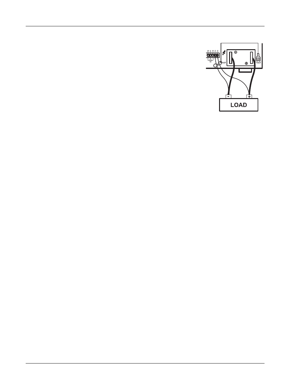
NOTE: The MPS includes a protection circuit which reduces the effect of open
sense leads during remote voltage sensing operation. If the +S lead opens, the
output voltage changes because it is sensed between +OUT and the negative
side of the load. If the –S lead opens, the output voltage changes because it is
sensed between the positive side of the load and –OUT. If both leads open, the
output voltage is sensed internally.
The procedure below configures the MPS for remote voltage sensing as shown
in Figure 2-3.
1. Turn off the unit.
2. If present, disconnect any wires between the +OUT and –OUT terminals
and the +S and –S connections on the MPS rear panel.
3. Connect the sense leads from the MPS +S and –S connections to the load.
Maintain polarity when making these connections.
CAUTION: Maintain polarity between +S and +OUT and –S and –OUT. The
+S and –S inputs control the output voltage. Improper polarity may apply
damaging voltages to the load.
4. Connect the ground shield to the mounting screw. Make sure that the shield does not come into electrical
contact with either magnet lead.
2.6 MULTIPLE AUTO-PARALLEL SETUP
Connect up to four MPS units in an auto-parallel configuration for increased output current capability. The
maximum total current allowed is the sum of the maximum currents of the individual units. For example four
623 MPS units provide 4
×
155 = 620 amps total current. The maximum total power is the sum of the
maximum power ratings of the individual units.
Assign each unit a unique address: 1 for MPS 1, 2 for MPS 2, etc. The MPS at address 1 polls the control bus
to determine if an auto-parallel configuration is present and how many MPS units are involved. When multiple
MPS units are present, MPS 1 sends the output current and voltage limits, ramp status, output current step
limit, and other operating parameters to the other MPS units so all units operate identically.
For two MPS configuration, each MPS is programmed for half of the total output current. This is true for the
ramp destination current and ramp rate. Each MPS contributes half the output current required. MPS 1
software polls MPS 2 to determine the total output current. The output voltage, current settings during a ramp,
and instrument status from MPS 1 are reported (since the values are the same for both units.)
NOTE: When multiple MPS units are present, install the Model 6228 persistent switch heater output option in
MPS 1 for proper operation.
An analog signal is also provided for remote activation of the output over voltage protection (OVP) circuit. The
signals connect in parallel so that the output OVP circuits of each MPS activate in unison.
CAUTION: Consult Lake Shore prior to operating multiple MPS units in auto-parallel mode.
Use the procedure below and see Figure 2-4 to connect multiple MPS units in auto-parallel configuration:
1. Turn off all units and completely disconnect power at the source before changing MPS configuration.
2. Determine which MPS to assign as MPS 1 and configure it as follows:
a. Locate the CAL AND ID DIP switches on the rear panel. Turn ON (up position) switches 1 and 4. Turn
OFF (down position) switches 2, 3, and 5 through 8. (Switch 4 ON designates multiple MPS operation.
Switches 3, 2, and 1 respectively OFF, OFF, and ON assign the MPS address as 1). Note that the
CAL AND ID switch numbers are upside down (as viewed from the rear panel). Switch 1 is on the right
and switch 8 is on the left. Take care to use the correct switch numbers.
b. Move the I MODE switch to the INTernal (up) position.
MPS Rear View
Maintain
polarity!
Connect -S
to -OUT and
+S to +OUT.
Figure 2-3. Remote
Sensing Connections