Lakeshore Learning Materials 622 User Manual
Page 20
Lake Shore Model 620/622/623/647 Magnet Power Supply User’s Manual
Setup & Connections
2-4
2.5.2
Shielding, Grounding, and Noise
For noise reduction, tightly twist and shield the leads from the MPS to the magnet. Connect the shield to the
MPS chassis as shown in Figure 2-3.
WARNING:
DO NOT place magnet leads in contact with other MPS/system connections or metal parts.
In some instances, the user's measurement leads may pick up noise from the magnet leads. Although this
common mode noise may affect the user's measurement it rarely affects the current in the magnet. If the
user's measurement is earth grounded, some improvement is almost always possible by tying the –OUT
terminal of the MPS to earth ground – either at the MPS chassis or, if the user's system has one, the common
system earth ground point.
WARNING: If the –OUT terminal is tied to earth ground, make certain the +OUT cable from the MPS
contacts no other earth ground point - it forces the MPS output current into this other ground point. If
the other ground point is a small wire, it may melt or catch fire.
2.5.3
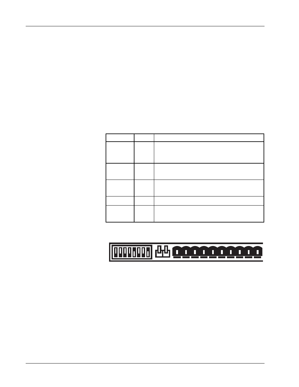
MPS Remote Inhibit and Fault Indicator Connections
The MPS has a Fault Indicator
(FLT) output and a discrete
Remote Inhibit (RI) input which
are both interface independent
and provide fault indication and
remote output shutdown in the
event of catastrophic failure.
The Fault Indicator relay contact
is open when the MPS detects
no faults. When the MPS
detects an internal fault, a
remote inhibit, or an output
inhibit, it lights the front panel
Fault LED and closes the relay
contact. The contact closure
alerts other system components
of the fault. In an auto-parallel
system (up to four MPS units
connected in parallel) these
signals connect in parallel
between each of the MPS units
(See Paragraph 2.6 for details
on connections between two
auto-parallel units). Make
connections to a rear panel
detachable terminal block
defined in Table 2-2 and Figure
2-1.
2.5.4
AC On Indicator
The MPS provides a discrete ON indicator. Terminals 5 and 6 on the terminal block connector, shown in
Figure 2-1 above, connect to relay contacts that close when the front panel circuit breaker is in the ON
position. There is also a front panel LED that lights when the MPS is ON and connected to AC power.
2.5.5 OVP
Connection
In auto-parallel MPS configurations, this connection synchronizes the firing of the Over Voltage Protection
(OVP) circuits of each MPS (see Paragraph 4.7.4). See Paragraph 2.6 and Figure 2-4 for auto-parallel
connections.
Table 2-1. RI, FLT, ON, and OVP Connections
TERMINAL LABEL
DEFINITION
1
2
RI+
RI–
Remote Inhibit – Active low, TTL-compatible input to
remotely force the output settings to 0 A and 1 V. Also
activate RI by shorting +RI to -RI with a relay contact closure
or a switch.
3
4
FLT+
FLT–
Fault Indicator – A relay contact that closes to indicate a
fault. Contact rating: 0.25 A resistive at 100 VDC, 3 W, 25
VA.
5
6
ON+
ON–
ON Indicator – A relay contact that closes to indicate when
the front panel circuit breaker is in the ON position. Contact
rating: 0.25 A resistive at 100 VDC, 3 W, 25 VA.
7
NONE
Factory Use Only. Do not connect to this terminal.
8
OVP
In auto-parallel MPS configurations, OVP ensures that the
activation of one MPS Over Voltage Protection circuit
activates all the other parallel MPS units' protection circuits.
1
2
3
4
5
6
7
8
9
10
+
-
+
-
+
-
OVP Im Vm
CAL AND ID
V
l
MODE
INT
V
l
EXT
RI
FLT
ON
See Table 5-1B for
DIP Switch Definitions
Figure 2-1. RI, FLT, ON and OVP Connections