000a, 999a – Lakeshore Learning Materials 622 User Manual
Page 36
Lake Shore Model 620/622/623/647 Magnet Power Supply User’s Manual
Operation
3-10
2. Enter these parameters in the Automatic Mode Screen:
MAG START: Magnet Start Current (only if
LAST END is unknown). For this example,
we assume an initial MPS hook-up to this
magnet and a previous magnet charge to
20 A.
MGT
END: Magnet End Current. Enter 30
A.
MGT
RATE: Magnet Charging Rate. Base this figure on the maximum magnet current supplied by the
magnet manufacturer. For this example, enter 0.4 A/S (amperes per second).
PERS
RATE: Persistence Switch Charging Rate. Base this figure on the maximum Persistence Switch
current (generally much higher than the magnet charging rate). Anything over approximately 20 A/S
appears instantaneous. For this example, enter 4 A/S.
3. Enter the following parameters in the Automatic Delay Screen (Function Menu 3).
RUN UP: The time between initial ramp up
to current and PSH activation (Persistence
Mode OFF). Enter 5 seconds.
PERS OFF: The time between PSH
activation (Persistence Mode OFF) and
initial ramp to setpoint. Enter 5 seconds.
RAMP END: The time between ramp up to setpoint and PSH deactivation (Persistence Mode ON). Enter
5 seconds.
PERS ON: The time between PSH deactivation (Persistence Mode ON) and initial ramp back to zero.
Enter 5 seconds.
4. Return to the Automatic
Mode Screen. Move to the
RUN line, then toggle to
activate Automatic Mode.
The MPS automatically runs
through the cycle as defined,
providing messages on the
bottom line of the display to
detail the current step of the
cycle. When complete, the
display returns to
STANDBY.
After determining proper system
Delay times, it is unnecessary to
visit the Delay Screen each time;
the delays store in non-volatile
memory. After the MPS
completes the cycle once, it
stores the ending current value
to LAST END. To make
subsequent changes to magnet
current simply enter a new MGT
END setpoint.
To pause a ramp or skip a time out, press either the Data Entry up or down key. To abort the operation, press
Escape. After an abort,
A U T O M A T I C M O D E :
¤ M G T S T A R T
M G T E N D
M G T R A T E
P E R S R A T E
L A S T E N D
P E R S I S T E N C E
R U N ¥
O U T P U T S :
*
+0.000A
: 0 . 0 0 0 A
: 0 . 0 0 0 A
: 1 . 0 0 0 A / S
: 1 . 0 0 0 A / S
: 0 . 0 0 0 A
: < O F F >
+ 0 . 0 0 1 V
S T A N D B Y
A U T O M A T I C M O D E D E L A Y S :
¤ R U N U P
P E R S O F F
R A M P E N D
P E R S O N
O U T P U T S :
*
+1.999A
: 6 0 S
: 6 0 S
: 6 0 S
: 6 0 S
L V L : + 1 4 . 4 i n
F L D : + 6 3 . 4 8 k G
+ 0 . 0 0 1 V
0
ON
OFF
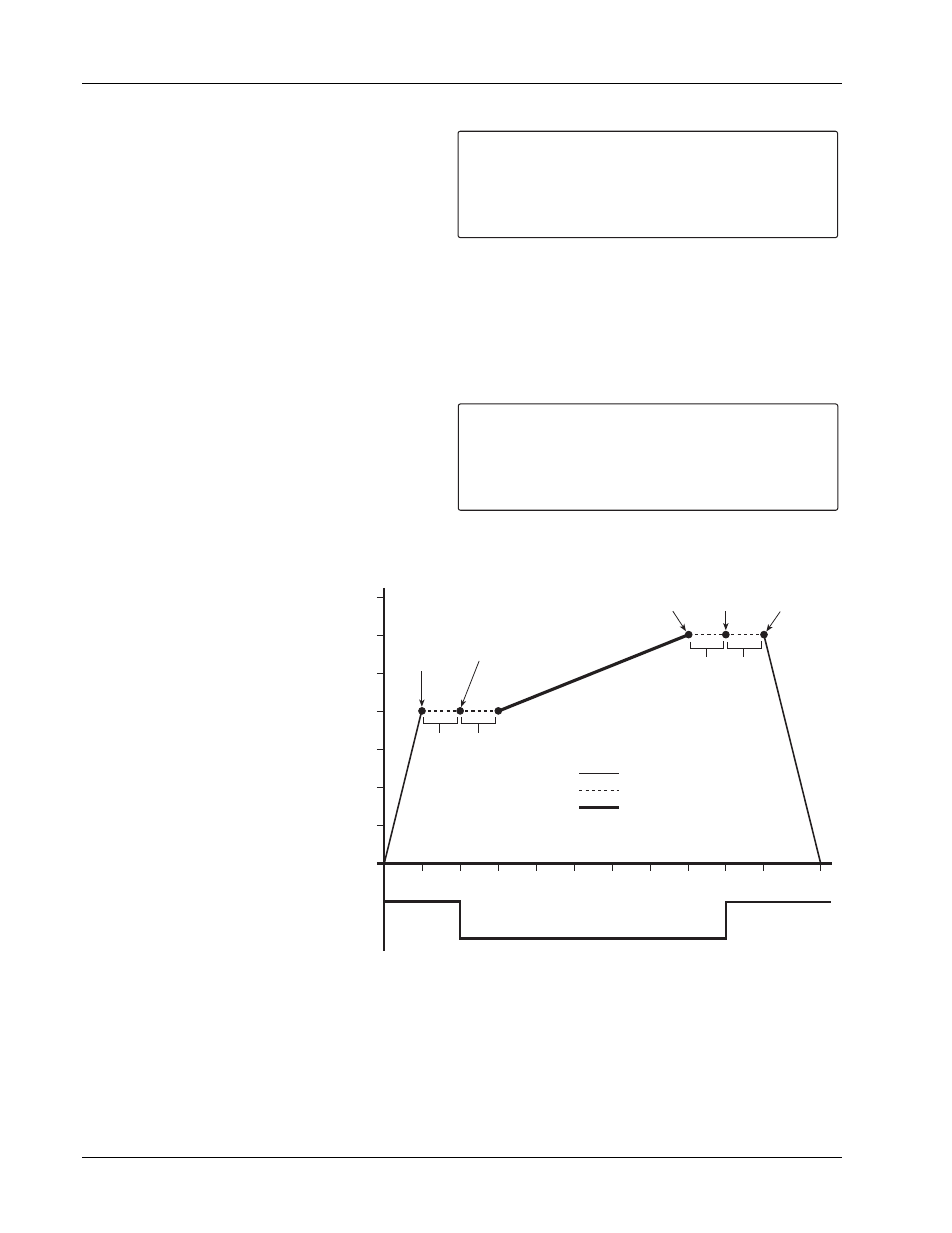
5
PERS RATE Ramp
Delay
MGT RATE Ramp
RAMP
UP
Delay
PERS
OFF
Delay
RAMP
END
Delay
PERS
ON
Delay
MGT
START
Persistence Off
(PSH On)
MGT
END
Persistence On
(PSH Off)
LAST
END
AUTOMATIC MODE
5
10
15
20
25
30
35
MPS Current Output (amperes)
P
e
rs
istence
Mode Status
10
15
20
25
30
35
40
45
50
57.5
Time (seconds)
Figure 3-2 Typical Automatic Mode Cycle