Lakeshore Learning Materials 622 User Manual
Page 21
Lake Shore Model 620/622/623/647 Magnet Power Supply User’s Manual
Setup & Connections
2-5
2.5.6
MPS Analog Current And Voltage Monitoring Connections
The MPS provides amplified and buffered
current and voltage monitor output signals
at the terminal block on the back panel.
Connect these signals to external meters
to indicate output current and voltage.
Obtain the Current Monitor signal through
connections to terminals 9 (Im) and 11 (m)
with positive output currents producing a
positive monitor voltage of 10 mV/A from
Im to m.
Obtain the Voltage Monitor signal through
connections to terminals 10 (Vm) and
11 (m) with positive terminal voltages
producing a positive monitor voltage of
10 mV/V from Vm to m.
2.5.7
External Current Programming
Remotely program MPS output current by
an external voltage or potentiometer.
Enable external analog programming via
the rear panel I MODE switch. When the I
MODE switch is in the INT I position,
external current mode is disabled. When
the I MODE switch is in the EXT I position,
the external programming voltage is
summed with the internal programming
voltage. Set the internal programming to
zero for external programming only. Apply
an external voltage from lp to m of 0 to
1.25 volts or use a 10 K
Ω
potentiometer to
control the output current over the entire
range. Make connections to rear panel
detachable terminal block defined in
Tables 2-3 and 2-4 and Figures 2-1 and 2-
2. The MPS produces 100 A of output
current for 1 V at the current programming
input.
NOTE: MPS protection circuits reduce the
effect of open external programming leads.
An open external programming lead forces
external programming voltage to
approximately 0 volts.
2.5.8
Remote Sense Connections
The factory configures the MPS to sense, but not control remote voltage. Call Lake Shore to reconfigure the
MPS to control voltage at the load. When using remote sense, the MPS measures voltage at the magnet
instead of at the MPS output terminals allowing a more accurate reading of magnet voltage by eliminating
voltage drops in the leads connecting the MPS to the magnet. If using remote sense, the MPS bases the
voltage at the voltage monitor output on the remote sense voltage instead of the MPS terminal voltage.
Use AWG #24, shielded, twisted pair wiring for sense leads to minimize pickup of external noise. Any noise
on the sense leads may appear at the unit output. Ground sense shield to the MPS back panel.
Make Remote Sense Connections to the rear panel detachable terminal block defined in Table 2-3 and
Figure 2-2.
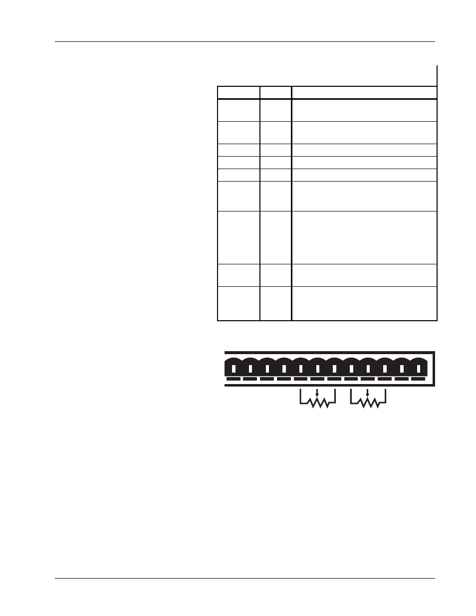
Table 2-2. Analog Monitoring, Programming,
and Remote Sense Connections
TERMINAL LABEL
DEFINITION
9
Im
Output Current Monitor – Voltage output
from Im to GND(M) is ±10 mV/A.
10
Vm
Output voltage monitor – Voltage output
from Vm to GND(M) is ±10 mV/V.
11
m
Monitor and program ground. GND(m).
12
Vp
Not Used.
13
+Vs
Not Used.
14
–Is
Negative voltage supply for
programming external current with a
potentiometer
15
Ip
Current programming input voltage.
Voltage input from Ip to GND(m)
produces ±100 A/V. Voltage may come
from a voltage source or from the center
tap of a potentiometer connected from -
Is to +Is.
16
+Is
Positive voltage supply for programming
external current with a potentiometer.
17
18
–S
+S
Remote voltage sense correction.
Correction for load lead drops of up to
0.5 V per lead.
10K
10K
7
8
9
10 11 12 13 14 15 16 17 18
OVP Im Vm m Vp +Vs -ls
lp +ls -S +S
Figure 2-2. Analog Monitoring , Programming,
and Remote Sense Connections