Error messages & troubleshooting – Lakeshore Learning Materials 622 User Manual
Page 67
Lake Shore Model 620/622/623/647 Magnet Power Supply User’s Manual
Error Messages & Troubleshooting
5-9
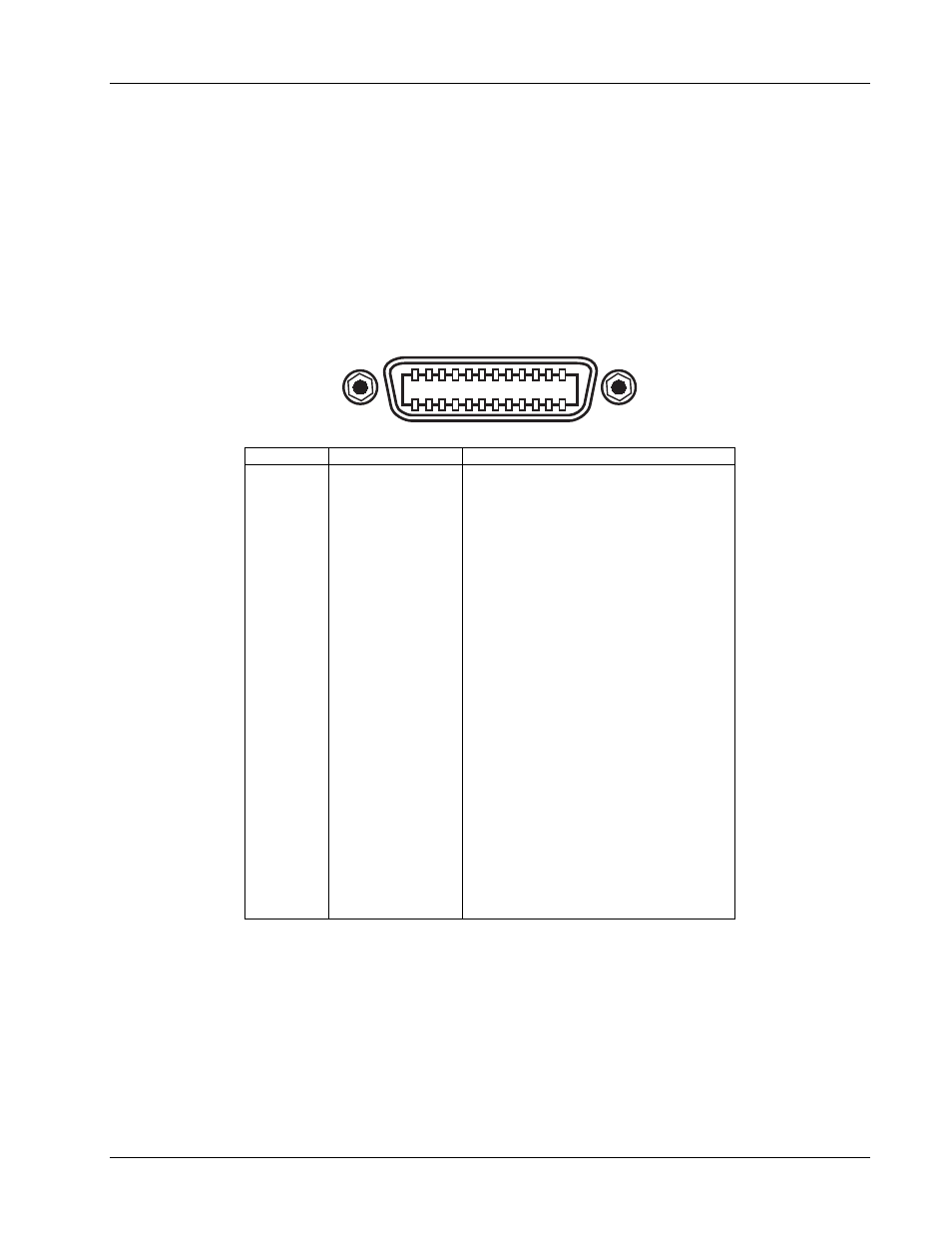
5.6 IEEE-488 INTERFACE CONNECTOR (WHEN MODEL 6224 OPTION IS PRESENT)
Connect to rear MPS IEEE-488 Interface connector with cables specified in the IEEE-488-1978 standard
document. The cable has 24 conductors with an outer shield. The connectors at each end are 24-way
Amphenol 57 Series (or equivalent) with piggyback receptacles to daisy-chain multiple devices. Secure
connectors in the receptacles by a pair of captive locking screws with metric threads.
The total length of cable allowed in a system is 2 meters for each device on the bus, or 20 meters total for a
maximum of 15 devices. The figure below and the table to the right shows the IEEE-488 Interface connector
pin location and signal names.
12
11
10
9
8
7
6
5
4
3
2
1
24
23
22
21
20
19
18
17
16
15
14
13
SH1 AH1 T5 L4 SR1 RL1 PP0 DC1 DT0 C0 E1
PIN SYMBOL
DESCRIPTION
1
2
3
4
5
6
7
8
9
10
11
12
13
14
15
16
17
18
19
20
21
22
23
24
DIO1
DIO2
DIO3
DIO4
EOI
DAV
NRFD
NDAC
IFC
SRQ
ATN
SHIELD
DIO5
DIO6
DIO7
DIO8
REN
GND 6
GND 7
GND 8
GND 9
GND 10
GND11
GND
Data Input/Output Line 1
Data Input/Output Line 2
Data Input/Output Line 3
Data Input/Output Line 4
End Or Identify
Data Valid
Not Ready For Data
Not Data Accepted
Interface Clear
Service Request
Attention
Cable Shield
Data Input/Output Line 5
Data Input/Output Line 6
Data Input/Output Line 7
Data Input/Output Line 8
Remote Enable
Ground Wire – Twisted pair with DAV
Ground Wire – Twisted pair with NRFD
Ground Wire – Twisted pair with NDAC
Ground Wire – Twisted pair with IFC
Ground Wire – Twisted pair with SRQ
Ground Wire – Twisted pair with ATN
Logic Ground
Figure 5-3. IEEE-488 Interface Connector