Lakeshore Learning Materials 622 User Manual
Page 71
Lake Shore Model 620/622/623/647 Magnet Power Supply User’s Manual
Options & Accessories
6-3
Locate the probe in a cavity that is 0.003 inch wider and 0.01 inch longer than the substrate, and with a depth
the same or slightly greater than the thickness of the package. Tack the leads outside the slot with GE-7031
varnish or other similar substance. Sparingly apply the mounting substance to the corners or a dot on each
side of the sensor to hold it in place. Avoid applying mounting substance on top of the sensor. Alternately, use
Kapton
®
tape or a mechanical cover over the top of the sensor to keep it in place. The tape or cover should
apply only light pressure to the sensor. If epoxy is the mounting substance, use it sparingly and use the same
type as is used in the sensor, Stycast
®
2850-FT epoxy. Never pot the probe.
A room temperature calibration over the range of ±30 kG comes with each probe. The calibration specifies the
terminating resistor (not included) required to maintain an accuracy of ±1% of reading up to ±30 kG and ±2%
of reading up to ±150 kG over the entire temperature range. For a terminating resistor, use a metal film
resistor with 1% or better accuracy mounted across the output voltage leads as close to the probe as is
practical. To extend the leads, use AWG 34 stranded copper with Teflon insulation (the same wire used on the
probe). Any impedance in the output leads acts as a voltage divider with the terminating resistor. Probe
reading reproducibility is within ±1% over repeated thermal cycling between 4.2 K and room temperature.
6.2.2
The Model MSA-410 and MST-410 Hall Sensors
Models MSA-410 and MST-410 gaussmeter probes are used with the Model 6476. Lake Shore offers a ten-
foot extension cable (Model MPEC-410-10).
6.2.3 Connections
The Model 6226/6476 has one rear panel 9-pin connector to interface with the
level and field probes. See Table 6-1.
6.2.4 Installation
The 6226/6476 Liquid Helium Level and Gaussmeter Input Option is factory-
installed if ordered with a MPS or may be field installed at a later date. For
field installation, use the procedure below:
WARNING
• This procedure is intended for trained service personnel who
understand electronic circuitry and the hazards involved. Do not
attempt this procedure unless qualified.
• To prevent shock hazard, turn off the instrument and disconnect AC
line power and all test equipment before removing cover.
1. Turn off the MPS and disconnect the power cord.
2. Locate the Optional Plug-In Board Slots on the MPS rear panel. Loosen the two screws that secure one of
the blank cover plates and remove the cover plate.
3. Slide the Model 6226/6476 board into the MPS with the board handle towards the bottom of the MPS.
Tighten the two screws that secure the board to the MPS rear panel.
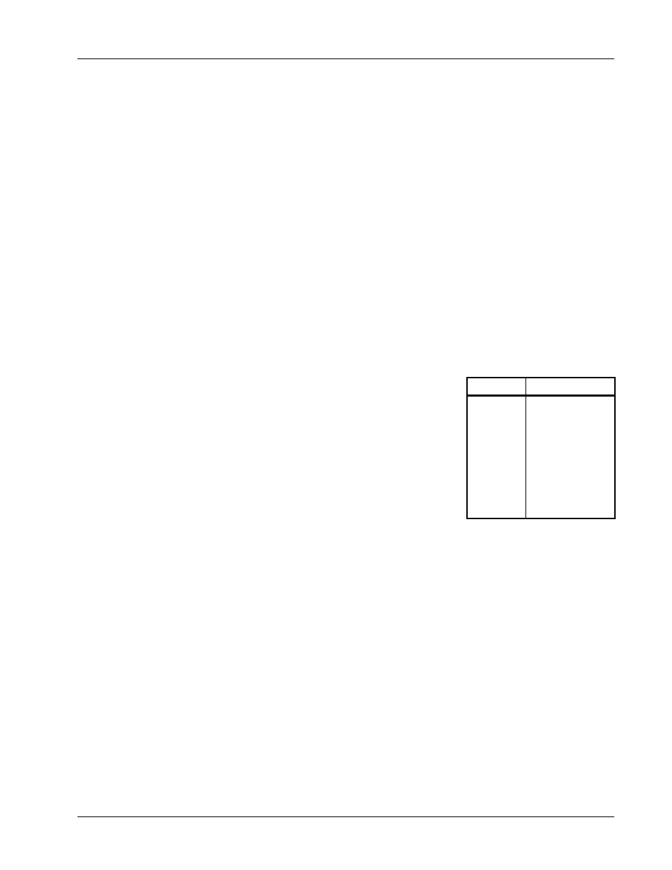
Table 6-1 Model 6226/6476
Connections
Terminal Description
1
2
3
4
5
6
7
8
9
Field –Current
Field –Voltage
Field +Voltage
Field +Current
Shield
Level –Current
Level –Voltage
Level +Voltage
Level +Current