Lenovo RD210 User Manual
Page 86
with
the
connector
on
the
system
board
and
press
down
on
the
assembly
until
it
is
seated
firmly
into
the
connector
on
the
system
board.
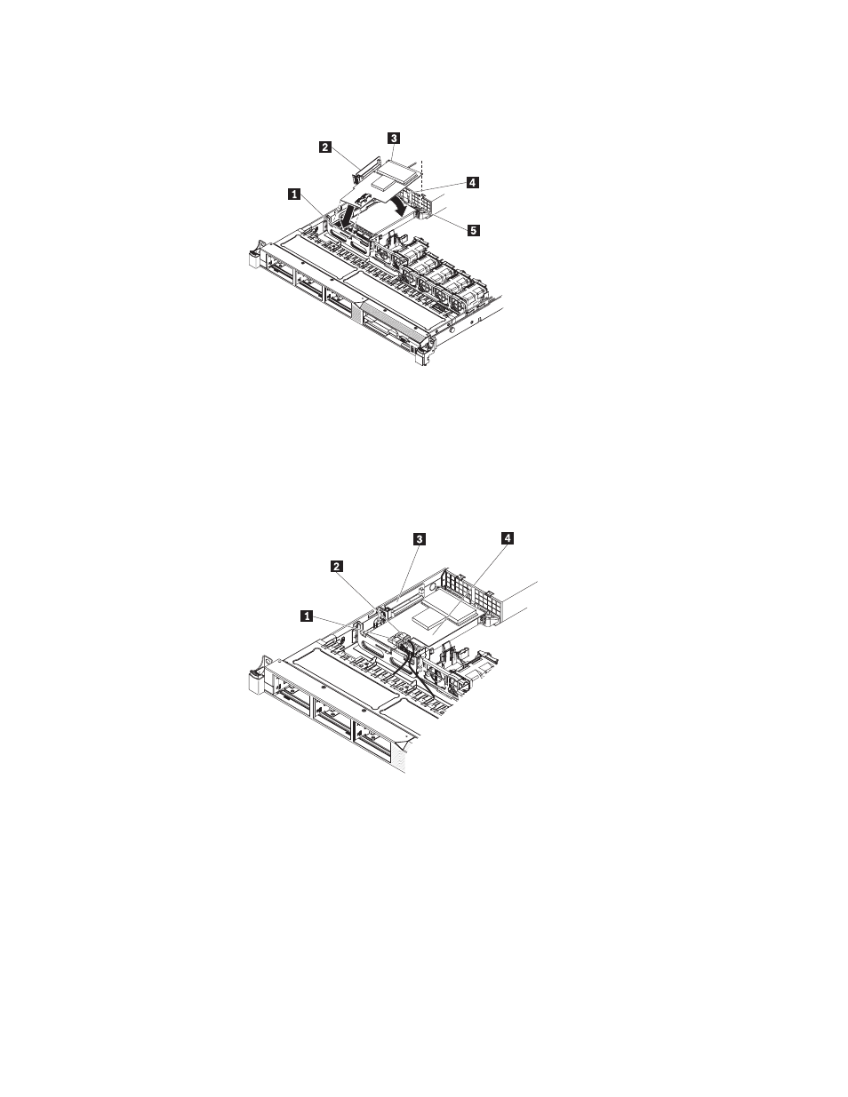
1
SAS/SATA
RAID
front
retention
bracket
2
SAS/SATA
RAID
riser
card
3
ServeRAID-MR10i
adapter
4
Plastic
tab
5
Alignment
post
8.
Route
the
signal
cables
from
the
drive
backplane
over
the
blue
adapter
retention
bracket
as
shown
in
the
following
illustration.
1
Connector
for
drive
bays
0-3
signal
cable
2
Connector
for
drive
bays
4-5
signal
cable
3
SAS/SATA
RAID
riser
card
4
ServeRAID-MR10i
controller
9.
Take
the
signal
cable
that
is
attached
to
the
drive
backplane
for
drive
bays
4
and
5
and
connect
it
to
the
RAID
controller
connector
that
is
closest
to
the
power
supply
cage.
Connect
the
other
signal
cable
so
that
is
attached
to
the
drive
backplane
for
drive
bays
0
through
3
and
connect
it
to
the
other
connector
on
the
controller.
The
following
illustration
show
how
to
route
the
signal
cables.
Note:
When
you
restart
the
server,
you
will
be
prompted
to
import
the
existing
RAID
configuration
to
the
new
RAID
controller.
70
ThinkServer
RD210
Types
3795,
3796,
3818,
and
3819:
Installation
and
User
Guide