Lenovo RD210 User Manual
Page 128
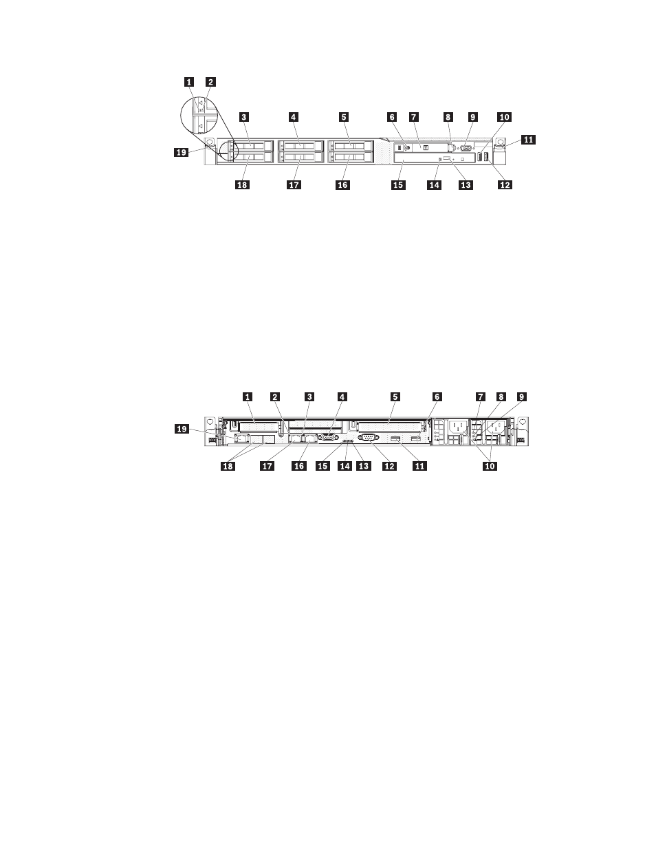
1
Hard
disk
drive
activity
LED
(green)
11
Rack
release
latch
2
Hard
disk
drive
status
LED
(amber)
12
USB
2
connector
3
Drive
bay
0
13
Optical
drive
eject
button
4
Drive
bay
2
14
Optical
drive
activity
LED
5
Drive
bay
4
15
Optical
drive
bay
6
Power-control
button
and
LED
16
Drive
bay
5
7
Operator
information
panel
17
Drive
bay
3
8
Operator
information
panel
release
latch
18
Drive
bay
1
9
Video
connector
19
Rack
release
latch
10
USB
1
connector
The
following
illustration
shows
the
LEDs
on
the
rear
of
the
server.
1
Slot
1,
PCI
Express
11
USB
3
connector
2
Ethernet
activity
LED
12
Serial
connector
3
Ethernet
link
LED
13
System-error
LED
(amber)
4
Video
connector
14
System-locator
LED
(blue)
5
Slot
2,
PCI
Express
15
Power-control
button
LED
(green)
6
USB
4
connector
16
Ethernet
2
connector
7
AC
LED
(green)
17
Ethernet
1
connector
8
DC
LED
(green)
18
Ethernet
connectors
3
and
4
(with
optional
2-port
Ethernet
card)
9
Power
supply
error
LED
(amber)
19
System
management
Ethernet
connector
10
Power
cord
connectors
You
must
turn
off
the
server
before
you
connect
or
disconnect
cables.
See
the
documentation
that
comes
with
any
external
devices
for
additional
cabling
instructions.
It
might
be
easier
for
you
to
route
cables
before
you
connect
the
devices
to
the
server.
Cable
identifiers
are
printed
on
the
cables
that
come
with
the
server
and
optional
devices.
Use
these
identifiers
to
connect
the
cables
to
the
correct
connectors.
112
ThinkServer
RD210
Types
3795,
3796,
3818,
and
3819:
Installation
and
User
Guide