2 8067 esi interface pinouts, 3 8067 information format, 8067 esi interface pinouts – Seagate Fibre Channel Interface User Manual
Page 119: 8067 information format
Fibre Channel Interface Manual, Rev. D
105
10.3.2
8067 ESI interface pinouts
In 8067, the ESI function becomes a bi-directional interface. Three pins are defined for control functions and
the remaining four pins become a 4-bit nibble interface. Table 58 is a mapping of the Select pins to the 8067
ESI interface function. 8067 specifies that open-collector type drivers be used for signals on the P_ESI and
Select lines.
10.3.3
8067 information format
ESI in 8067 mode is transferred on the ESI interface a nibble (4 bits) at a time. Refer to Table 59 for the trans-
fer order in bits and Table 60 for byte order.
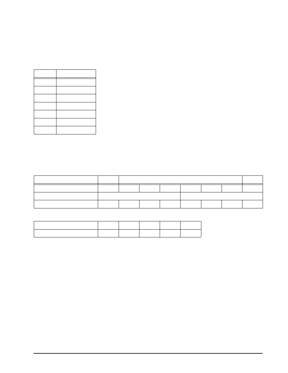
Table 58:
SFF 8067 ESI pinouts
Pin
ESI function
SEL 6
–DSK_WR
SEL 5
–DSK_RD
SEL 4
–ENCL_ACK
SEL 3
Data (3)
SEL 2
Data (2)
SEL 1
Data (1)
SEL 0
Data (0)
Table 59:
Bit order in 8067 mode ESI transfers
MSB
LSB
Bit order byte
7
6
5
4
3
2
1
0
Transfer order on ESI interface
First Nibble
Second Nibble
Bit order is ESI data
D(3)
D(2)
D(1)
D(0)
D(3)
D(2)
D(1)
D(0)
Table 60:
Byte order in 8067 mode ESI transfers
Byte order in SCSI transfer
0
1
..........
n – 1
n
Byte order is ESI transfer
first
second
..........
n – 1
n