Figure a-6, Table a-7, Table a-8 – Sun Microsystems SERVER 1290 User Manual
Page 72
60
Netra 1290 Server Installation Guide • May 2006
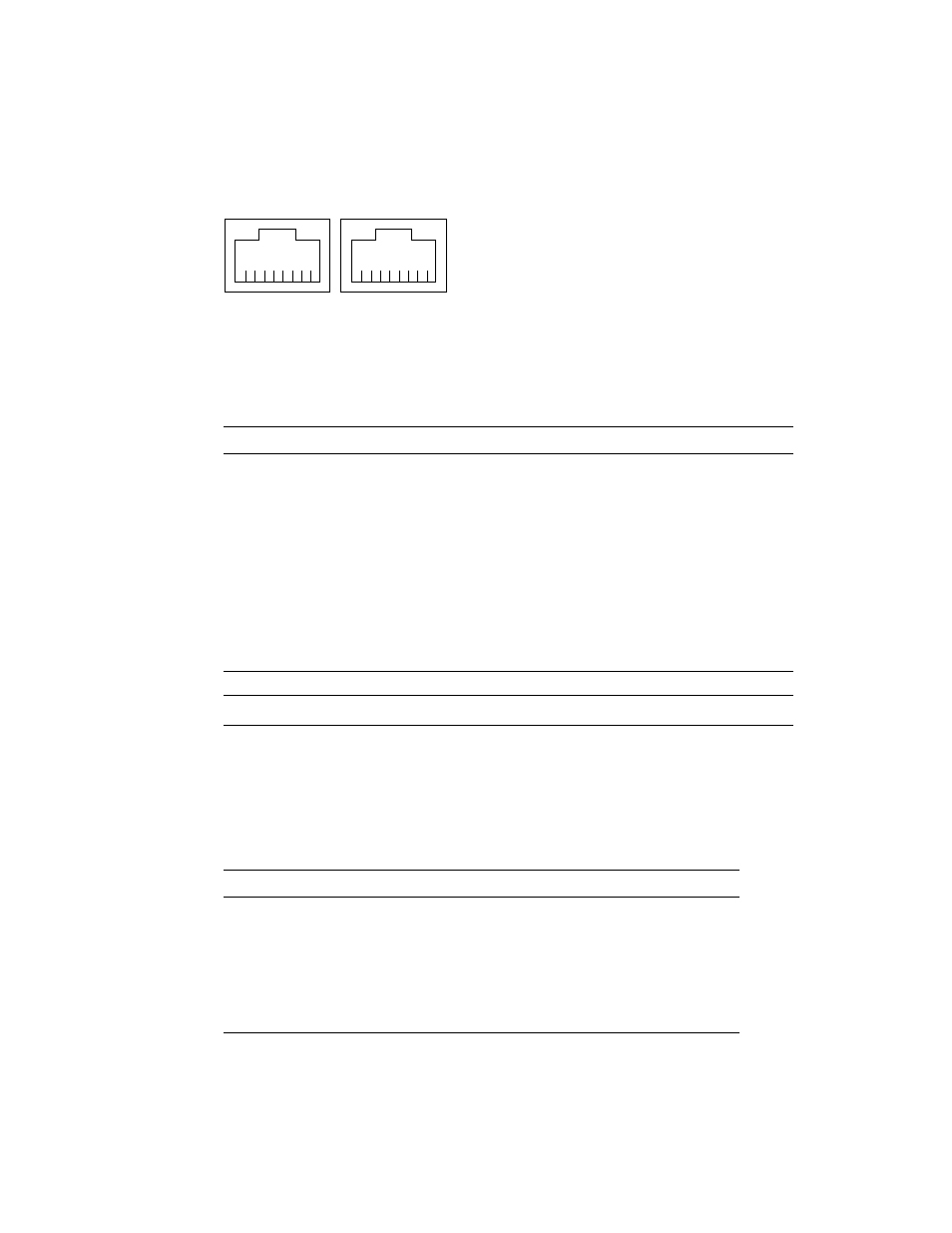
FIGURE A-6
RJ-45 Serial Connectors
Note –
Serial port B is reserved.
lists the settings needed to use the LOM Serial A connection. The
configuration of this port cannot be changed. Be sure to check the manufacturer’s
documentation for your specific terminal server. Communication on LOM Serial A is
subject to interruption by the LOM device. Refer to the Netra 1290 Server System
Administration Guide, 819-4374.
TABLE A-7
RJ-45 Serial Connector Pinout
Pin
Signal
1
RTS
2
DTR
3
TXD
4
Signal Ground
5
Signal Ground
6
RXD
7
DSR
8
CTS
TABLE A-8
Default Settings for Connecting to LOM Serial A
Parameter
Setting
Connector
LOM Serial A
Rate
9600 baud
Parity
No
Stop bits
1
Data bits
8
LOM Serial A
Serial B
1
8
1
8