Communication setup, Check the results displayed on the menu display, System setup – Sanyo VSP-9000 User Manual
Page 47: English
English
System Setup
46
Communication Setup
C
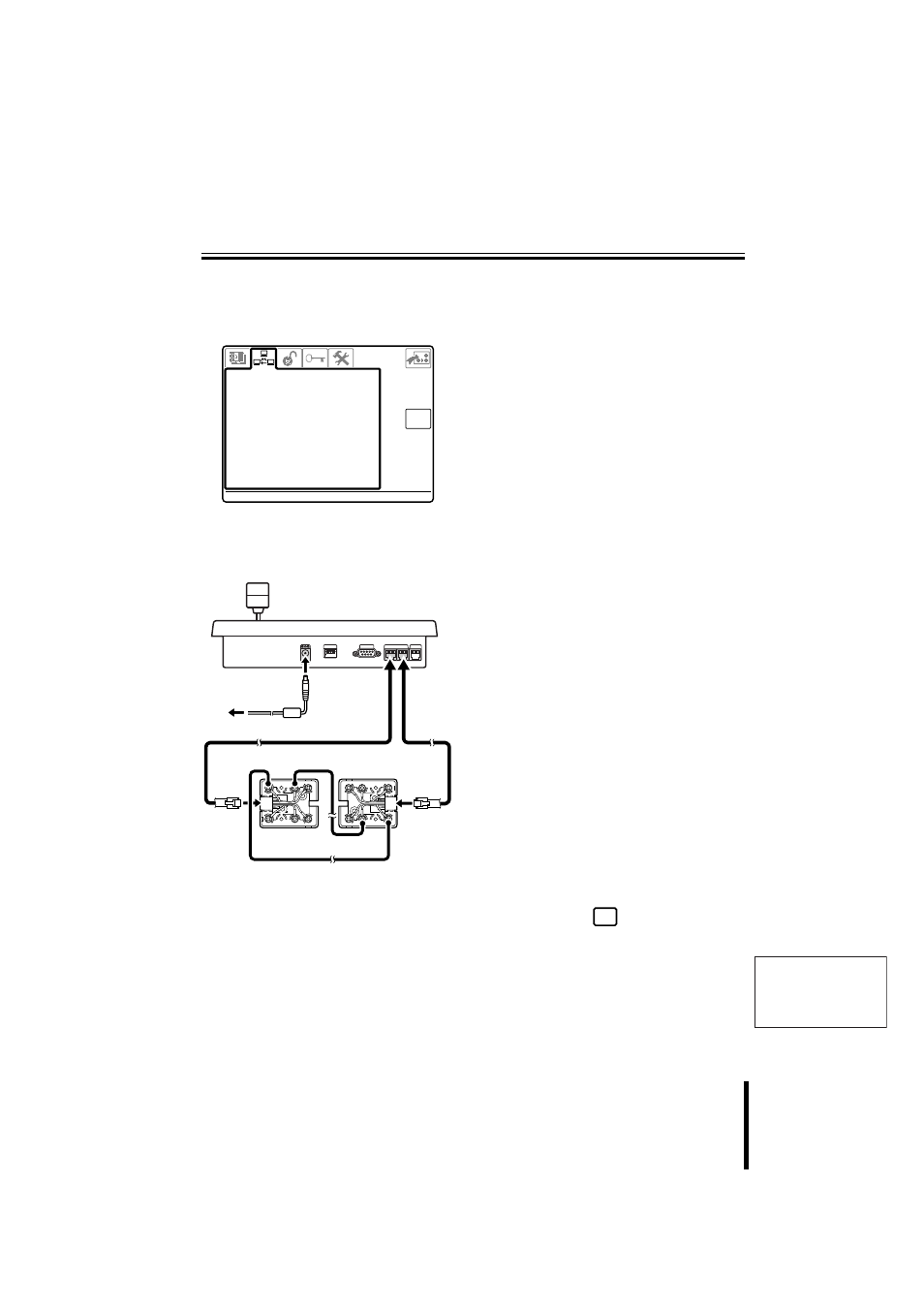
3–SERIAL TESTS
(Communication output test for
video communication terminal and
camera communication terminal)
Remove all lines connected to this unit, and
use two modular cables and two
communication converter connectors to
connect as shown below.
1
Connect test cables to each
camera communication
terminal (TELEMETRY A and
B) on the rear panel.
2
Check the results displayed on
the menu display.
B<------>A:
Normal
B<------?A:
Line B has normal reception, but Line A
has a reception problem.
B?------>A:
Line A has normal reception, but Line B
has a reception problem.
When a problem is indicated, repeat the
test with TELEMETRY A connected to
VIDEO, and with TELEMETRY B
connected to VIDEO. The test results are
displayed as follows.
B?------?A:
The line is not functioning. No
transmission or reception.
B?------>A:
Transmission is possible, but no
reception.
B<------?A:
Reception is possible, but no
transmission.
B<------?A:
The line has normal transmission and
reception.
• When connecting V and A, or V and B,
this is displayed as follows.
V<------>A
V<------>B
3
When the test is complete,
press the
button to return
to the Menu screen.
esc
3 - S E R I A L T E S T S
3 - S E R I A L T E S T S
U n d e r t e s t ! ! !
V :
V : ? ? B :
B : ? ? A :
A : ? ?
? - - - - - - - - - ?
C O M M U N I C A T I O N S
C O M M U N I C A T I O N S
VIDEO
COM
SW
ON
1 2 3 4
A
B
TELEMETRY
12V
WH
B
L
S
L
O
R
B
R
B
K
Y
L
R
D
G
R
WH
B
L
S
L
O
R
B
R
B
K
Y
L
R
D
G
R
White
White
Yellow
Yellow
esc