Rear – Sanyo VSP-9000 User Manual
Page 11
English
Preparation
10
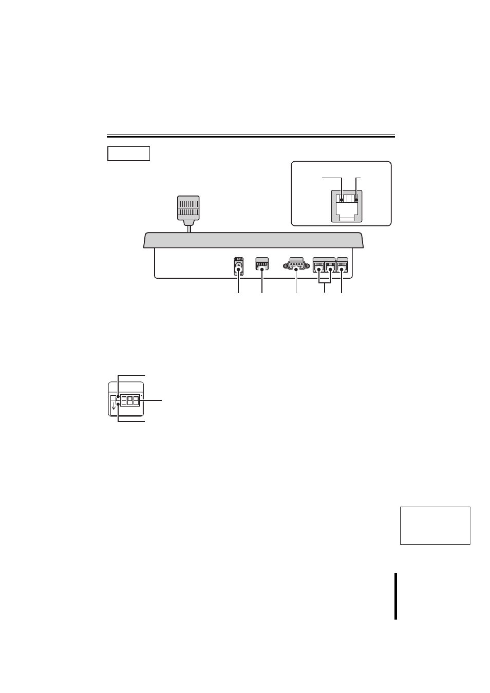
Part Names
1
Power terminal
Connect the DC terminal on the AC adapter
provided.
2
Dipswitch (SW)
Used for PC settings, communication settings,
or terminate settings on this unit.
3
PC connection terminal
(COM: RS-232C)
Use for connecting to a PC.
Install software on the provided CD-ROM to a
connected PC to add other languages, etc.
Use the language selection in system setup to
select an added language. This changes the
menu display language.
4
Camera communication
terminal (TELEMETRY A/B)
Connect a provided or separately purchased
modular cable to this terminal.
• Terminal A: Connect a camera.
• Terminal B: Connect a camera.
5
Video communication terminal
(VIDEO)
Connect video equipment (multiplexer, hard
disk digital recorder, etc.)
When connecting this unit with video
equipment, always use the provided modular
cable and communication conversion
connector.
VIDEO
COM
SW
ON
1 2 3 4
A
B
TELEMETRY
12V
1
2
3
4
5
Rear
A Signal
RS485 (RJ-11) Terminal
B Signal
SW
ON
1 2 3 4
When using as a system
controller, set to this position.
(OFF)
When using the provided PC
software. (ON: P60)
Use for ON/OFF settings for
each terminate setup.