JVC VR-609 User Manual
Page 22
-- 22 --
VR-609
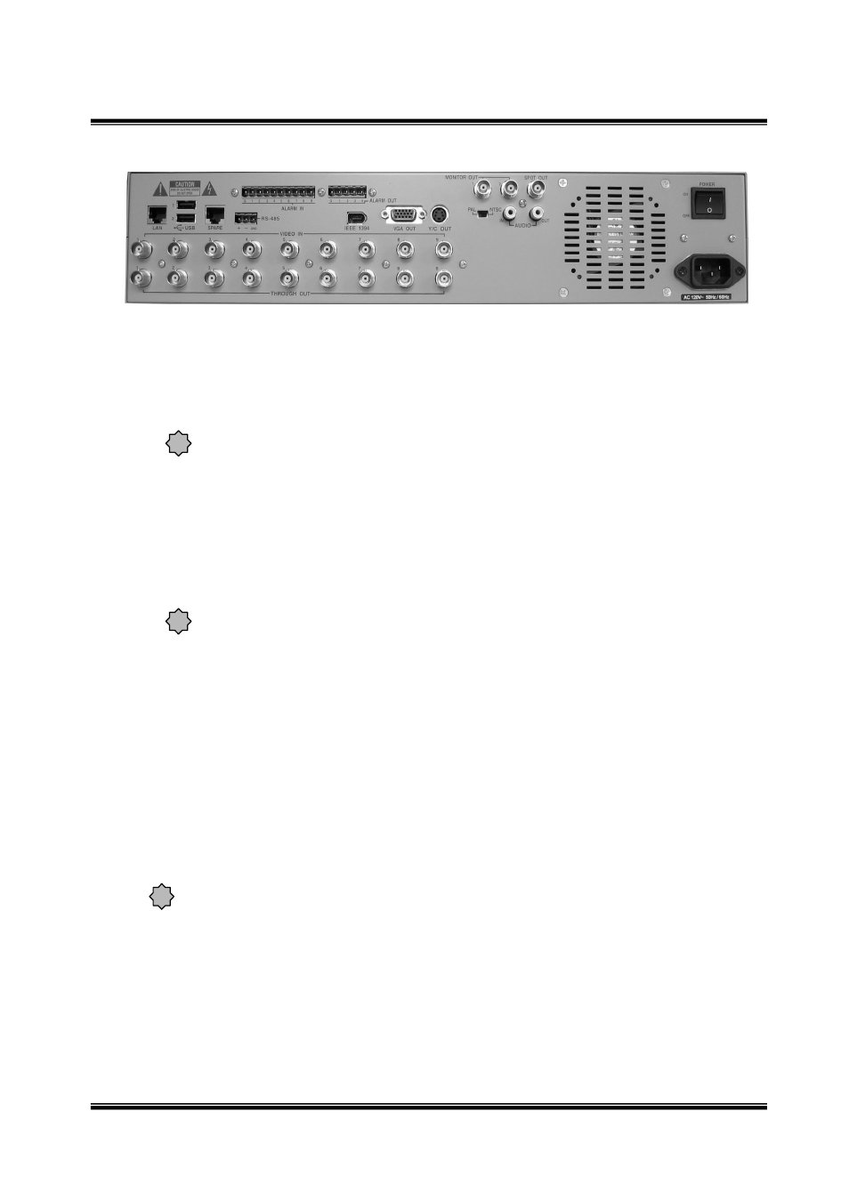
■ Rear
① LAN : Enables screen search and control via Network. (Please use a category 5
cable with a shield.)
② USB Port 1,2 : For backup with external FDD or memory stick. It does not work both
USB1 & 2 at the same time. Please use one of them.
The USB connector on this equipment corresponds to USB 1.1. A FDD or a flash
memory are connectable.
③ REMOTE : Allows connection of external remote controllers.
④ RS-485 : For connecting with external Pan/Tilt camera. The maximum cable length of
RS-485 is 1.2 km. (Please use a twisted-pair cable with a shield.)
⑤ ALARM IN : For alarm input. (Please use a shielded cable.)
ALARM OUT : For alarm output. (Please use a shielded cable.)
⑥ IEEE 1394 Port: Possible to extend storage space or backup by adding external
IEEE1394 or CDRW.
⑦ VGA OUT : Possible to connect with computer monitor.
(LCD can not be used when video signal mode is set as PAL.)
Please set-up in Menu before use this connector.
⑧ Y/C OUT : Outputs contents of monitor output as a S-VIDEO signal.
⑨ MONITOR OUT 1,2 (Composite) : Menu appears at the time of menu setting and
displays when screen search or recording.
⑩ SPOT OUT (Composite) : Outputs video which is set-up from the menu.
⑪ MODE(PAL/NTSC) : Selects input video signal mode.
If you change PAL/NTSC, once it carries out operate-off. Operate-on is carried
out, and a message "Video mode was changed! " is displayed and it shows a
"Press 'OK' to Reset All Previous Data. Otherwise, change NTSC/PAL in rear side
and then press 'Cancel'.". Select "OK", changes video signal mode.
When PAL/NTSC is changed, former record data is deleted!
An administrator password is reset when the PAL/NTSC mode is changed. Please
disable a password setting before changing the PAL/NTSC mode.
When PAL/NTSC mode is changed with a password setting enable, please use a
default password "1234".
⑫ AUDIO : I/O for audio recording/playback.
⑬ VIDEO IN BNC & THROUGH OUT (CH1 ∼ CH9)
: Inputs asynchronous video signal 1.0Vp-p.( 75 ohm )
: Loop out is changed to HI-Z automatically.
⑭ POWER Switch : This is the main power switch.
⑮ AC INLET : For connecting with provided power cord.
!
・Please turn off the power when you connect external IEEE1394 with DVR.
・If you connect external HDD with external CDRW, impossible to recognize.
!
Please turn off the power when you connect external USB with DVR.
!
①
③
②
④
⑥
⑤
⑦
⑨
⑧
⑩
⑫
⑪
⑬
⑭
⑮