Installing your new unit, Basic connections, Pg. 18 – JVC DR-M10 User Manual
Page 18: Pg. 18, 1, Check the contents, Install the unit, Connect the unit to a tv, Connect the unit to power source
Filename [DR-M10U_06-1Name.fm]
Masterpage:Left0
18
EN
Page 18
March 5, 2004 11:50 am
INSTALLING YOUR NEW UNIT
Basic Connections
It’s essential that your unit be properly connected.
A
Check the contents.
Make sure the package contains all of the accessories
listed in “SPECIFICATIONS” on page 109.
B
Install the unit.
Place the unit on a stable, horizontal surface.
C
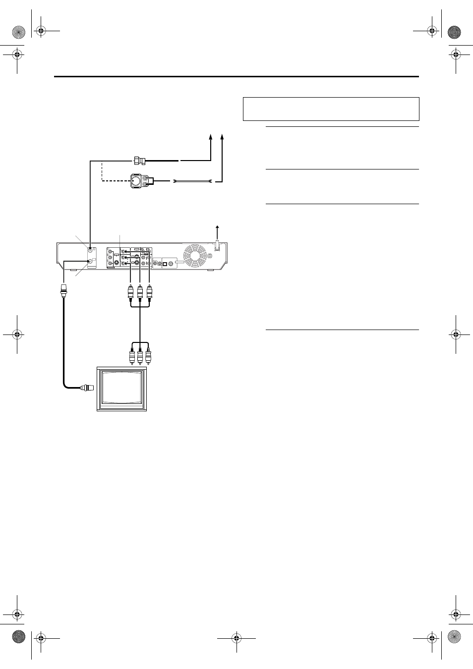
Connect the unit to a TV.
A Disconnect the TV antenna from the TV.
B Connect the TV antenna cable to the ANTENNA IN
connector on the rear panel of the unit.
C Connect the supplied RF cable between the
ANTENNA OUT connector on the rear panel of the
unit and the TV’s antenna connector.
D Connect the supplied audio/video cable between the
AUDIO/VIDEO OUTPUT connectors on the rear
panel of the unit and the TV’s audio/video input
connectors.
● Set your TV to AV mode.
● For switching the TV’s mode, refer to the instruction manual of
your TV.
D
Connect the unit to power source.
Plug the end of the AC power cord into an AC outlet. This
unit performs Plug & Play Set automatically. (
● The clock and tuner channels will automatically be set when
the antenna is connected and when the AC power cord is first
connected to an AC outlet. (If “AUTO” and the channel
indicator are displayed on the front display panel before the
unit is powered on, the clock and tuner channels are being set
automatically. Wait for the time to be displayed on the front
display panel before turning on the unit.)
NOTES:
● It requires the RF connection to enjoy TV programs.
● The playback image is not displayed without one of the
following: A/V, S-Video, or Component Video connection.
1
PCM STREAM
AV COMPU LINK
CABLE BOX
LEFT
AUDIO
RIGHT
LEFT
VIDEO
S-VIDEO
VIDEO
S-VIDEO
L-1
L-1
L-2
L-2
AUDIO
RIGHT
COMPONENT
COAXIAL
OPTICAL
Y
PB
PR
DIGITAL OUT
OUTPUT
INPUT
IN
OUT
ANTENNA
Antenna or Cable
Matching transformer
(not supplied)
Coaxial cable
ANTENNA
OUT
AUDIO/VIDEO
OUTPUT
AC Outlet
RF cable
(supplied)
Back of unit
ANTENNA
IN
Audio/video cable
(supplied)
Flat feeder
TV
AC Power Cord
To 75 ohm
Terminal
To Audio/video
input connectors
THESE STEPS MUST BE COMPLETED BEFORE ANY
VIDEO OPERATION CAN BE PERFORMED.
DR-M10U_06-1Name.fm Page 18 Friday, March 5, 2004 11:51 AM