Rear view – JVC DR-M10 User Manual
Page 13
Masterpage:Right-No-Heading
EN
13
Filename [DR-M10U_06-1Name.fm]
Page 13
March 5, 2004 11:50 am
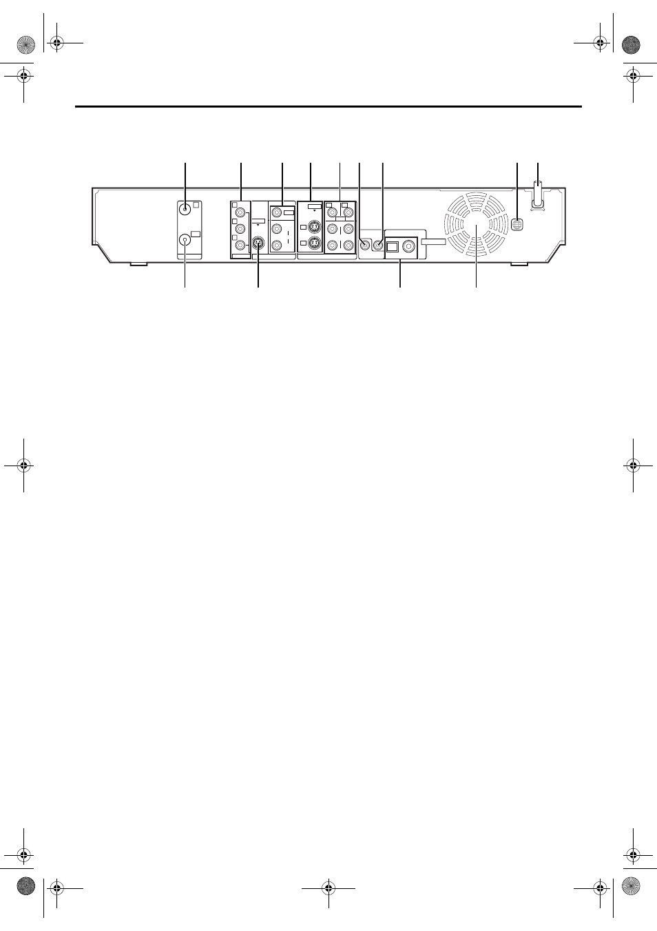
REAR VIEW
A Antenna Input Connector (ANTENNA IN)
B Component Video Output Connectors
(COMPONENT OUTPUT)
C Video/Audio Output Connectors (VIDEO/
D S-video Input Connector (S-VIDEO INPUT)
E Video/Audio Input Connectors (VIDEO/AUDIO
INPUT (L-1/L-2))
F Cable Box Control Connector (CABLE BOX)
G AV COMPU LINK Connector
H Region Number Label
I Mains Power Cord
J Antenna Output Connector (ANTENNA OUT)
K S-video Output Connector (S-VIDEO OUTPUT)
L Digital Audio Output Connectors
(DIGITAL OUT (COAXIAL/OPTICAL))
੬ pg. 90, 95
M Cooling Fan
● This prevents the temperature from rising inside the unit.
Do not remove it.
● Install the unit so as not to block the area around the fan.
● The cooling fan on the rear of the unit may be activated even if the
unit is turned off in the following cases;
— in the REC LINK standby mode (
੬
pg. 71)
— when “AUTO CLOCK” is set to “ON” (
੬
pg. 24)
PCM STREAM
AV COMPU LINK
CABLE BOX
LEFT
AUDIO
RIGHT
LEFT
VIDEO
S-VIDEO
VIDEO
S-VIDEO
L-1
L-1
L-2
L-2
AUDIO
RIGHT
COMPONENT
COAXIAL
OPTICAL
IN
Y
P
B
P
R
OUT
DIGITAL OUT
ANTENNA
OUTPUT
INPUT
1
B
F G
H I
K
J
L
M
A
C
D
E
DR-M10U_06-1Name.fm Page 13 Friday, March 5, 2004 11:50 AM