Connection diagram for front panel connector, Front panel connector, Table 24 – Intel D865PCD User Manual
Page 53: Table 25, 2 front panel connector
Technical Reference
53
2.8.3.1 Auxiliary Front Panel Power/Sleep/Message-Waiting LED Connector
Pins 1 and 3 of this connector duplicate the signals on pins 2 and 4 of the front panel connector.
Table 24. Auxiliary Front Panel Power/Sleep/Message-Waiting LED Connector
Pin Signal
Name
In/Out
Description
1
HDR_BLNK_GRN
Out
Front panel green LED
2 Not
connected
3
HDR_BLNK_YEL
Out
Front panel yellow LED
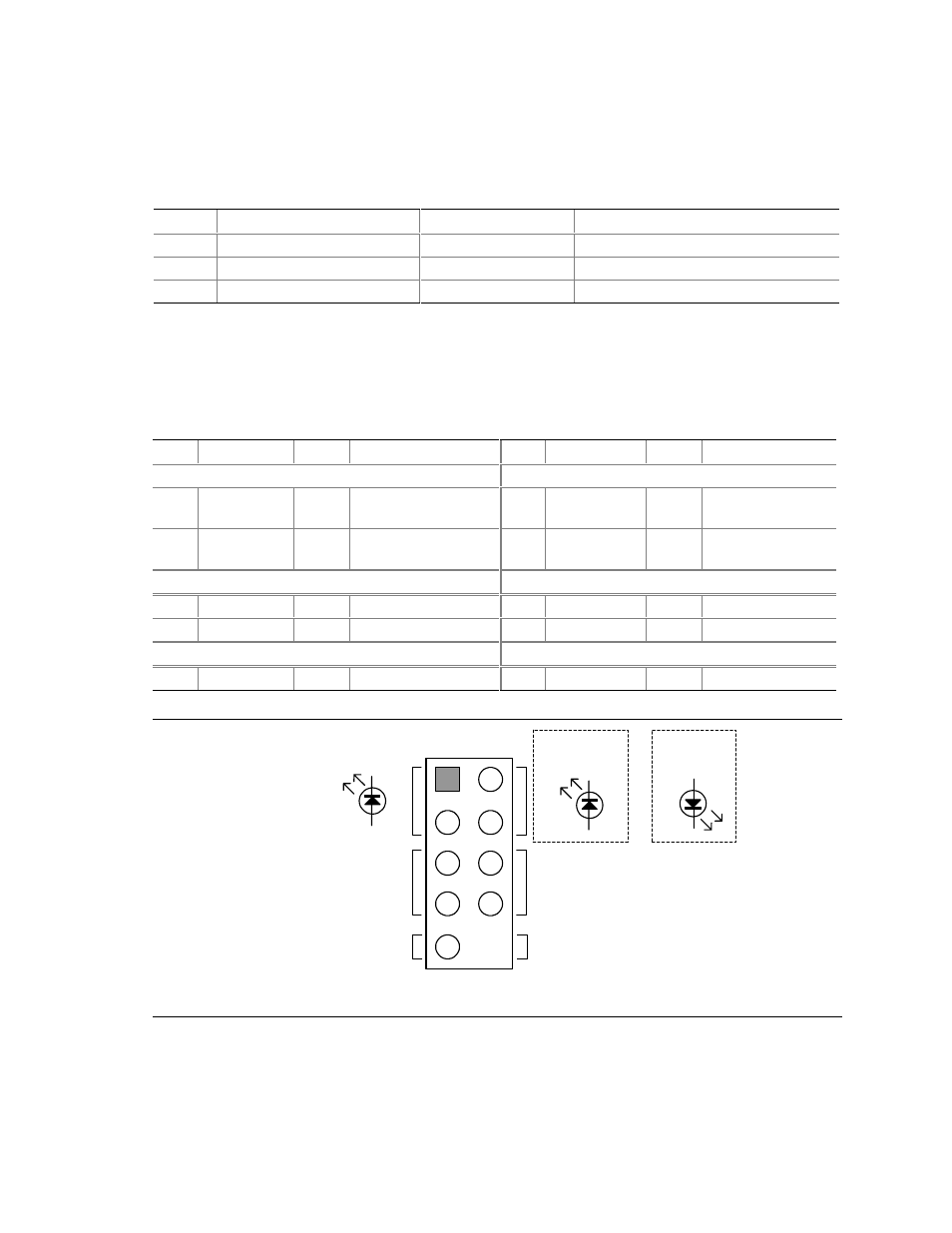
2.8.3.2 Front Panel Connector
Table 25. Front Panel Connector
Pin Signal
In/Out
Description
Pin Signal
In/Out
Description
Hard Drive Activity LED
Power LED
1
HD_PWR
Out
Hard disk LED pull-up
(750
Ω) to +5 V
2 HDR_BLNK_
GRN
Out
Front panel green
LED
3
HAD#
Out
Hard disk active LED
4
HDR_BLNK_
YEL
Out
Front panel yellow
LED
Reset Switch
On/Off Switch
5 Ground
Ground
6 FPBUT_IN In Power
switch
7 FP_RESET#
In Reset
switch
8 Ground
Ground
Power Not
Connected
9
+5
V Power
10
N/C
Not
connected
Single-colored
Power LED
OM16110
8
6
4
2
9
7
5
3
1
Hard Drive
Activity LED
Reset
Switch
+5 V DC
N/C
Power
Switch
Dual-colored
Power LED
Figure 13. Connection Diagram for Front Panel Connector