Rear chassis fan connector, Atx12v power connector, Processor fan connector – Intel D865PCD User Manual
Page 49: Main power connector, Table 18, Table 19, Table 20, Table 21
Technical Reference
49
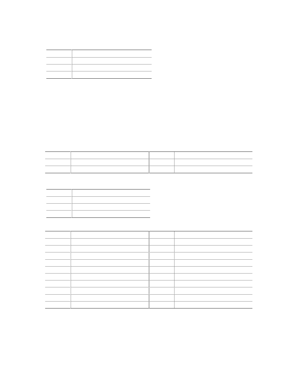
Table 18. Rear Chassis Fan Connector
Pin Signal
Name
1 Control
2
+12 V
3 REAR_TACH_OUT
#
INTEGRATOR’S NOTES
• Use only ATX12V-, SFX12V-, or TFX12V-compliant power supplies with the Desktop Board
D865PCD. ATX12V, SFX12V, and TFX12V power supplies have an additional power lead
that provides required supplemental power for the processor. Always connect the 20-pin and
4-pin leads of ATX12V, SFX12V, and TFX12V power supplies to the corresponding connectors
on the desktop board, otherwise the board will not boot.
• Do not use a standard ATX power supply. The board will not boot with a standard ATX power
supply.
Table 19. ATX12V Power Connector
Pin Signal
Name
Pin Signal
Name
1 Ground
2 Ground
3 +12
V
4 +12
V
Table 20. Processor Fan Connector
Pin Signal
Name
1 Control
2 +12
V
3 CPU_FAN_TACH
Table 21. Main Power Connector
Pin Signal
Name
Pin Signal
Name
1
+3.3 V
11
+3.3 V
2
+3.3 V
12
-12 V
3 Ground
13
Ground
4
+5 V
14
PS-ON# (power supply remote on/off)
5 Ground
15
Ground
6 +5
V
16
Ground
7 Ground
17
Ground
8
PWRGD (Power Good)
18
No connect
9
+5 V (Standby)
19
+5 V
10 +12
V
20 +5
V