3 block diagram, Block diagram, Block – Intel D865PCD User Manual
Page 14: Diagram
Intel Desktop Board D865PCD Technical Product Specification
14
1.1.3 Block
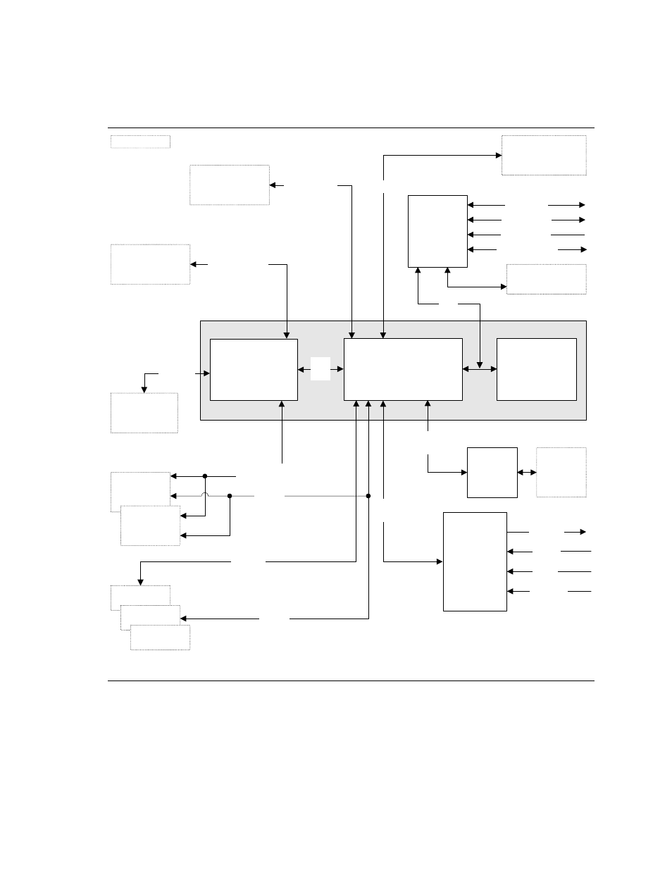
Diagram
Figure 2 is a block diagram of the major functional areas of the board.
Intel 865P Chipset
Intel 82801EB
I/O Controller Hub
(ICH5)
Intel 82865P
Memory Controller
Hub (MCH)
4 Mbit
Firmware Hub
(FWH)
AHA
Bus
System Bus
(400/533 MHz)
mPGA478
Processor Socket
Parallel ATA IDE
Connectors (2)
Diskette Drive
Connector
LPC Bus
I/O
Controller
PS/2 Keyboard
PS/2 Mouse
Parallel Port
Serial Port
Parallel ATA
IDE Interface
LPC
Bus
OM17046
Realtek
ALC202
Audio Codec
Mic In
CD-ROM
Line In
LAN
Connector
10/100
LAN PLC
CSMA/CD
Unit Interface
AGP
Interface
Universal 0.8/
1.5 V AGP 3.0
Connector
= connector or socket
PCI Bus
SMBus
AC
Link
Back Panel/
Front Panel
USB Ports
USB
Dual-Channel
Memory Bus
SMBus
PCI Slot 1
PCI Slot 2
PCI Slot 3
Line Out
Channel A
DIMM
Channel B
DIMM
Figure 2. Block Diagram
- 41210 (64 pages)
- 8xC251TQ (20 pages)
- ENTERPRISE PRINTING SYSTEM (EPS) 4127 (84 pages)
- U3-1L (20 pages)
- 80960HA (104 pages)
- X58 (54 pages)
- ESM-2850 2047285001R (91 pages)
- ATOM US15W (54 pages)
- D915GVWB (4 pages)
- XP-P5CM-GL (28 pages)
- AX965Q (81 pages)
- CORETM 2 DUO MOBILE 320028-001 (42 pages)
- CV700A (63 pages)
- 80C188EA (50 pages)
- X25-M (28 pages)
- XP-P5IM800GV (26 pages)
- IB868 (60 pages)
- D865GVHZ (88 pages)
- IB865 (64 pages)
- Altera P0424-ND (1 page)
- 8086-2 (30 pages)
- IXDP465 (22 pages)
- IWILL P4D (104 pages)
- GA-8I955X PRO (88 pages)
- FSB400 (PC2100) (96 pages)
- D845GLAD (4 pages)
- NAR-3041 (1 page)
- 87C196CA (136 pages)
- G52-M6734XD (74 pages)
- A96134-002 (10 pages)
- Express Routers 9000 (8 pages)
- 82540EP (45 pages)
- D865GLC (94 pages)
- IB850 (69 pages)
- MB898RF (62 pages)
- Arima LH500 (78 pages)
- V09 (33 pages)
- I/O Processor (22 pages)
- M600 (110 pages)
- SE7520JR2 (63 pages)
- SERVER BOARD S5520HCT (30 pages)
- Extensible Firmware Interface (1084 pages)
- GA-8IPXDR-E (70 pages)
- D845EBG2 (4 pages)
- AW8D (80 pages)