Intel OCPRF100 MP User Manual
Page 84
OCPRF100 MP Server System Technical Product Specification
Revision 1.0
77
NOTES:
Default values are marked with the "†" symbol.
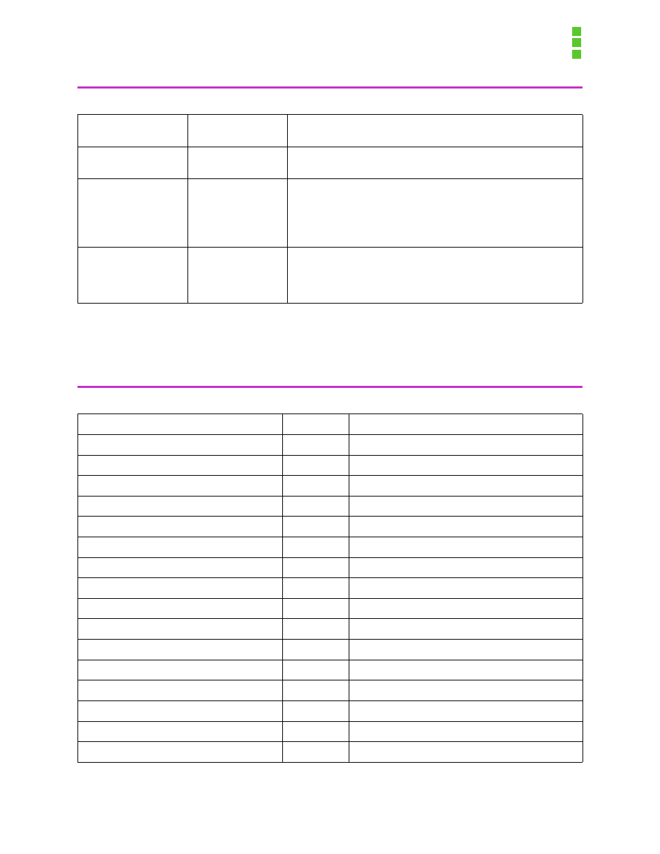
LBA Mode Control
Disabled
Enabled
Displays status of Logical Block Access. Autotyped by BIOS.
32 Bit I/O
Disabled†
Enabled
Enables 32-bit IDE data transfers.
Transfer Mode
Standard
Fast PIO 1
Fast PIO 2
Fast PIO 3
Fast PIO 4
Selects the method for transferring data to/from the drive. Auto-
typed by BIOS.
Ultra-DMA Mode
Disabled
Mode 0
Mode 1
Mode 2
Selects the Ultra-DMA mode used for transferring data to/from the
drive. Autotyped by BIOS.
Table 6-5: Processor Information Submenu
Feature
Option
Description
Left Processor 1 Stepping ID
Displays the stepping of the processor.
Left Processor 1 L2 Cache Size
Displays the size of the L2 cache.
Left Processor 2 Stepping ID
Displays the stepping of the processor.
Left Processor 2 L2 Cache Size
Displays the size of the L2 cache.
Left Processor 3 Stepping ID
Displays the stepping of the processor.
Left Processor 3 L2 Cache Size
Displays the size of the L2 cache.
Left Processor 4 Stepping ID
Displays the stepping of the processor.
Left Processor 4 L2 Cache Size
Displays the size of the L2 cache.
Right Processor 1 Stepping ID
Displays the stepping of the processor.
Right Processor 1 L2 Cache Size
Displays the size of the L2 cache.
Right Processor 2 Stepping ID
Displays the stepping of the processor.
Right Processor 2 L2 Cache Size
Displays the size of the L2 cache.
Right Processor 3 Stepping ID
Displays the stepping of the processor.
Right Processor 3 L2 Cache Size
Displays the size of the L2 cache.
Right Processor 4 Stepping ID
Displays the stepping of the processor.
Right Processor 4 L2 Cache Size
Displays the size of the L2 cache.
Table 6-4. IDE Submenu