Invacare 9000 SL User Manual
Page 48
9000 Series
48
Part No. 1056953
4. Securely tighten the bolt and locknut or socket screws securing the wheel lock to
the wheelchair frame.
5. Engage the wheel lock.
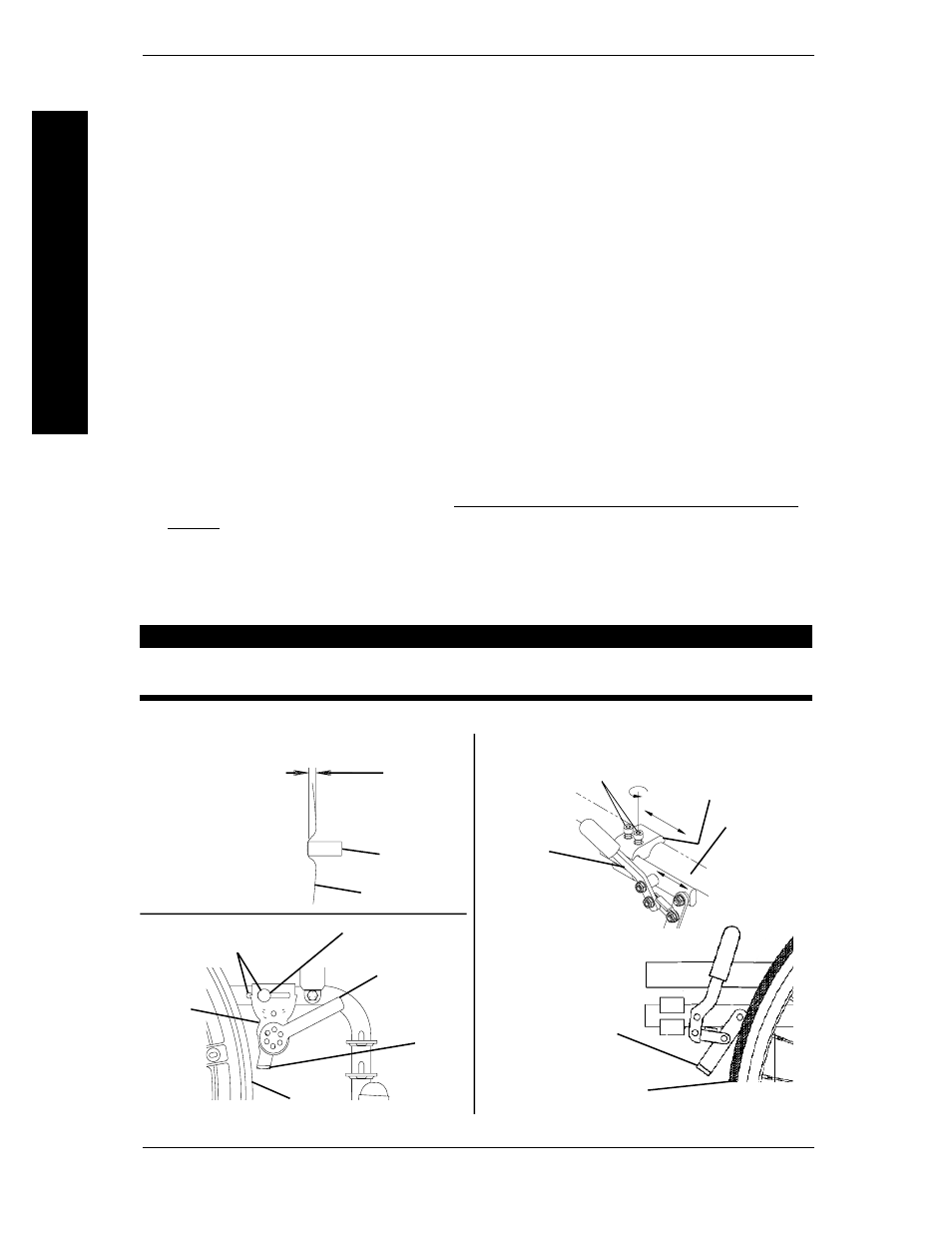
6. Measure the distance the wheel lock is embedded into the tire as shown in DETAIL
"A" of FIGURE 4.
NOTE: Any wheel lock adjustment should embed the wheel lock shoe at least 1/8-inch (3/16-inch
if pneumatic tire) into the tire when engaged.
7. Repeat STEPS 1-6 until the wheel lock shoe embeds the tire 1/8-inch (3/16-inch for
pneumatic tires) and HOLDS the occupied wheelchair in place when pushed.
8. If the measurement of 1/8-inch (3/16-inch for pneumatic tires) can not be achieved,
Perform one (1) of the following:
A. BOLT-ON WHEEL LOCKS - Remove the bolt and locknut that secure the
wheel lock to the wheelchair frame and mount the wheel lock in the remaining
mounting position.
B. CLAMP-ON WHEEL LOCKS - Proceed to STEP 9.
9. If wheel lock is unable to properly engage the wheel it may be necessary to install
wheel lock shoe extensions. Refer to INSTALLING WHEEL LOCK SHOE EXTEN-
SIONS in this section of the manual.
10. Repeat STEPS 1-9 for the opposite wheel lock.
11. Engage both wheel locks and ensure the occupied wheelchair is held in place when
pushed.
WARNING
If wheel locks do not hold the occupied wheelchair in place contact a
qualified technician. - othewise injury or damage may occur.
FIGURE 4 - ADJUSTING THE PATIENT OPERATED WHEEL LOCKS
Socket Screws
Wheel Lock
Wheelchair
Frame
BOLT-ON WHEEL LOCKS
CLAMP-ON WHEEL LOCKS
Wheel Lock
Clamp
DETAIL "A" -
WHEEL LOCK
SHOE
ENGAGEMENT
1/8-inch
(3/16-inch
pneumatic tires)
Tire
Wheel Lock
Shoe
Wheel Lock Handle
Bolt and Locknut
Mounting Positions
Wheel
Lock
Shoe
Rear
Wheel
Wheel
Lock
Rear Wheel
Wheel
Lock Shoe
ANTI-TIPPERS/WHEEL LOCKS
SECTION 8
ANTI-TIPPERS/WHEEL
LOCKS