Panel description, Front panel, Eheadphone jack [phones] accepts headphones – Icom IC-756 User Manual
Page 4
1
1
PANEL DESCRIPTION
■
Front panel
TIMER
POWER
TRANSMIT
PHONES
ELEC-KEY
MIC
TUNER MONITOR
NB
NR
AF
BAL
NR
RF/SQL
MIC GAIN RF POWER
COMP
KEY SPEED BK-IN DELAY
S
Po
0
10
1
1 1.5
2
3
5
9
+20 +40
+60dB
25
50
100
SWR
ALC
F-1
SSB
F-2
F-3
F-4
F-5
CW
RTTY
AM
FM
HF/50MHz TRANSCEIVER
i756
1ß
VFO
VFO
14.195.000
VFO
VFO
USB
USB
USB
14.100.00
14.100.00
14.205.000
14.205.000
USB
USB
USB
14.100.00
14.100.00
56
56
ß
T X
T X
FILTER
SCAN
MEMORY
SET
VOX
VOX
OFF
OFF
COMP
COMP
OFF
OFF
SCOPE
ANT
ANT
1
METER
METER
Po
Po
P.AMP
P.AMP
OFF
OFF
ATT
ATT
OFF
OFF
AGC
AGC
MID
MID
2.4k
2.4k
9
2.8k
2.8k
455
455
12:34
12:34
q
w
e
r
t
!3
!4
!5
!6
!7
y
i !0!1 !2
o
u
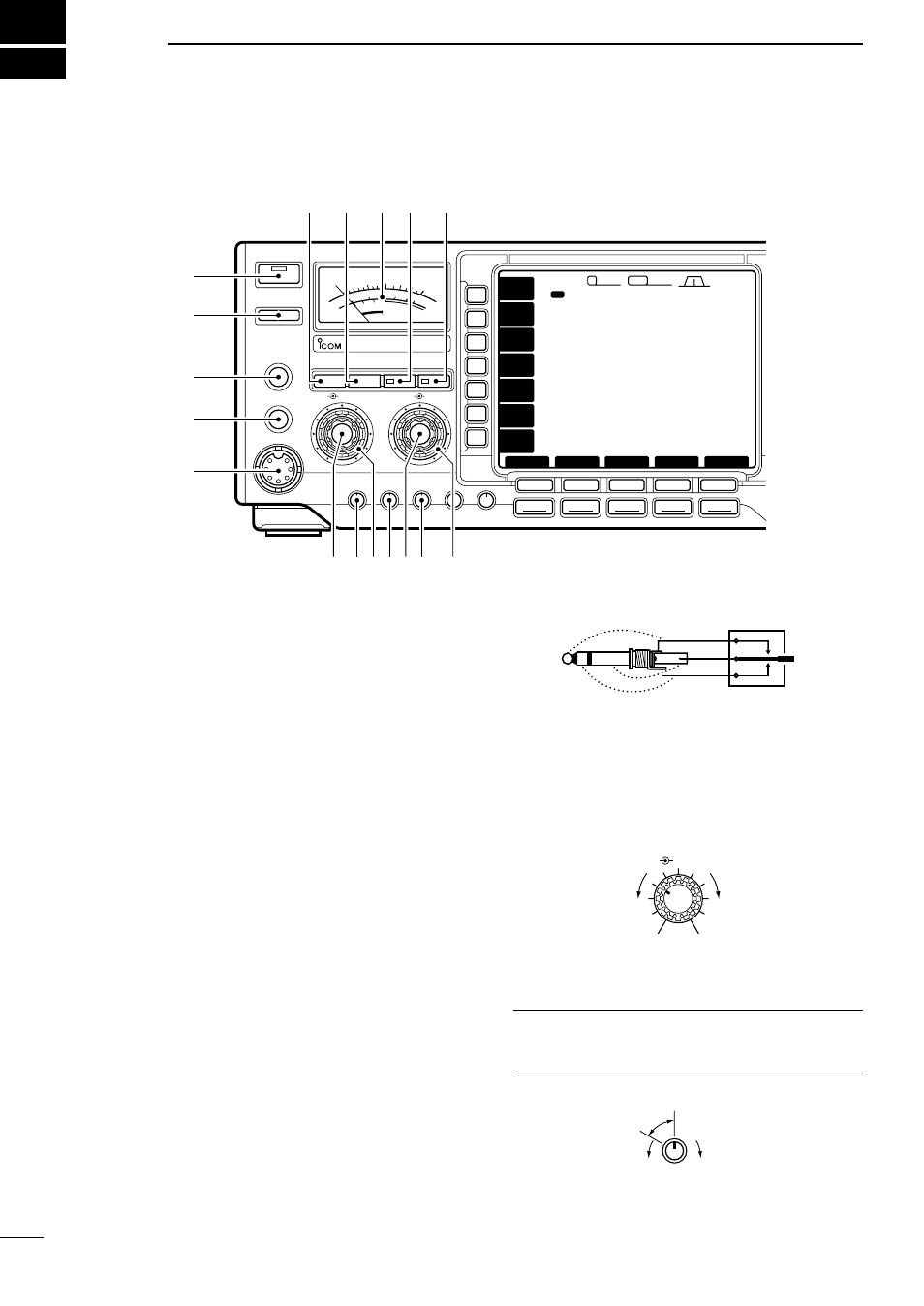
q
POWER SWITCH [POWER/TIMER]
• Push momentarily to turn power ON.
- Turn the optional DC power supply ON in advance.
• Push momentarily to toggle the timer function ON
and OFF. (p. 52)
- The power switch lights while the timer function is ON.
• Push for 2 sec. to turn power OFF.
w
TRANSMIT SWITCH [TRANSMIT]
Selects transmitting or receiving.
- The [TX] indicator lights red while transmitting and the
[RX] indicator lights green when the squelch is open.
e
HEADPHONE JACK [PHONES]
Accepts headphones.
- When headphones are connected, the internal speaker
or connected external speaker does not function.
r
ELECTRONIC KEYER JACK [ELEC-KEY] (p. 35)
Accepts a paddle to activate the internal electronic
keyer for CW operation.
- Selection between the internal electronic keyer, bug-key
and straight key operation can be made in keyer set
mode. (p. 35)
- A straight key jack is separately available on the rear
panel. See [KEY] on p. 11.
- Keyer polarity (dot and dash) can be reversed in keyer
set mode. (p. 35)
- 4-channel memory keyer is available for your conve-
nience. (p. 36)
t
MICROPHONE CONNECTOR [MIC]
Accepts the supplied or optional microphone.
- See p. 68 for appropriate microphones.
- See p. 8 for microphone connector information.
y
AF CONTROL [AF] (inner control)
Varies the audio output level from the speaker.
u
MIC GAIN CONTROL [MIC GAIN]
Adjusts microphone input gain.
✔
How to set the microphone gain.
Set the [MIC] control so that the ALC meter sometimes
swings during normal voice transmission in SSB mode.
Increases
Decreases
Recommended level for
an Icom microphone
MIC GAIN
AF
RF/SQL
No audio output
Max. audio output
Decreases
Increases
(dot)
(com)
(dash)