Remote jack (ci-v) information, Ci-v connection example, Data format – Icom IC-756 User Manual
Page 23: Command table
Description
Command
Frequency setting
05
Operating mode
LSB
USB
AM
CW
RTTY
FM
06
VFO mode selection
MAIN
↔
SUB
MAIN = SUB
Dualwatch OFF
Dualwatch ON
Main readout selection
Sub readout selection
07
Memory mode selection
Memory channel selection
08
Memory write
Memory transfer to VFO
Memory clear
09
0A
0B
Scan stop
Start programmed/memory scan
Start programmed scan
Start
∂
F scan
Start fine programmed scan
Start fine
∂
F scan
Start
memory
scan
Start
select memory
scan
0E
Split OFF
Split ON
0F
[TS] OFF (10 or 1 Hz step)
[TS] ON (1 kHz step)
[TS] ON (5 kHz step)
[TS] ON (9 kHz step)
[TS] ON (10 kHz step)
10
[ANT1] selection
[ANT2] selection
[ANT1/RX] selection
[ANT2/RX] selection
12
00 or 0000
01 or 0100
0001
0101
00
01
02
03
04
00
01
00
01
02
03
12
13
22
23
—
—
—
—
Mch no. (BCD)*
2
—
B0
B1
C0
C1
D0
D1
00
01
02
03
04
05
Data*
1
Sub command
20
2
INSTALLATION AND CONNECTIONS
■
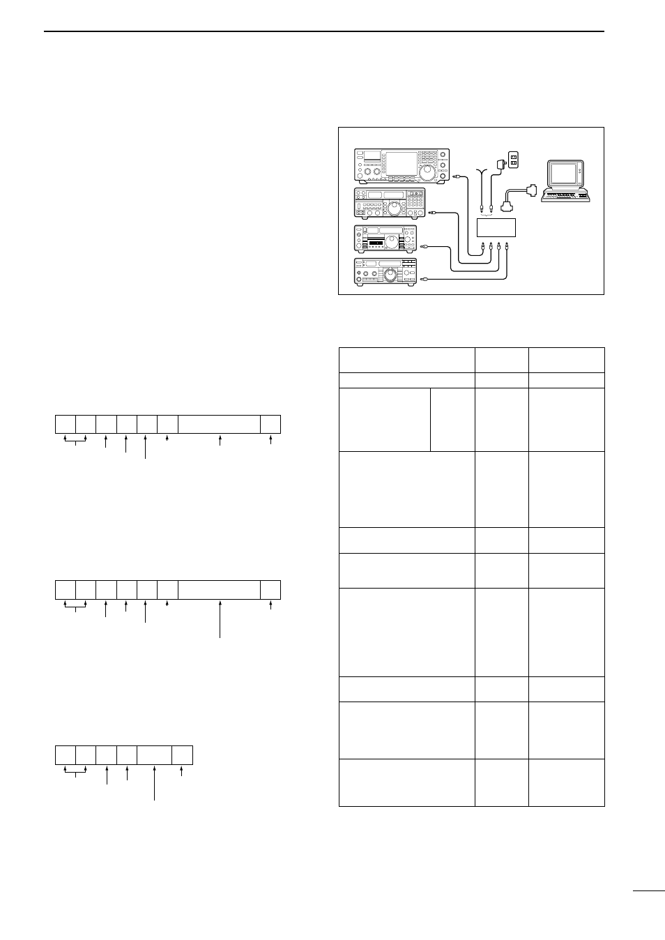
Remote jack (CI-V) information
• CI-V connection example
The transceiver can be connected through an optional
CT-17
CI-V LEVEL CONVERTER
to a personal computer
equipped with an RS-232C port. The Icom Communi-
cation Interface-V (CI-V) controls the following func-
tions of the transceiver.
Up to four Icom CI-V transceivers or receivers can be
connected to a personal computer equipped with an
RS-232C port. See p. 60 for setting the CI-V condition
using set mode.
• Data format
The CI-V system can be operated using the following
data formats. Data formats differ according to com-
mand numbers. A data area or sub command is added
for some commands.
IC-756
9–15 V DC
Personal
computer
ct- 17
• Command table
*1 Frequency data arrangement (BCD code)
10 Hz, 1 Hz, 1 kHz, 100 Hz, 100 kHz, 10 kHz,
10 MHz, 1 MHz, 1 GHz then 100 MHz
*2 Scan edge channel P1=0100, P2=0101
Controller
’s address
FE FE E0 50 Cn Sc Data area
(e.g. fd)
FD
Preamble code
(fixed)
Command number
Sub command number
BCD code area
End of message code
FE FE 50 E0 Cn Sc Data area
(e.g. fd)
FD
Preamble code
(fixed)
Controller
’s address
IC-756
’s address
(selectable in set mode)
IC-756
’s address
(selectable in set mode)
FE FE E0 50 FB/FA FD
Preamble code
(fixed)
Command number
(see table)
Sub command number
(see table)
BCD code frequency or
memory channel data
(See table)
End of message code
Controller
’s address
IC-756
’s address
(selectable in set mode)
CONTROLLER TO IC-756
IC-756 TO CONTROLLER
OK or NG MESSAGE TO CONTROLLER
OK code (FB) or
NG code (F
A)
End of message code