Rear panel – Icom IC-756 User Manual
Page 14
q
RECEIVE ANTENNA CONNECTOR [RX ANT]
(p. 15)
Connects a 50
Ω
general coverage antenna with an
RCA connector.
w
TUNER CONTROL SOCKET [TUNER] (p. 15)
Accepts the control cable from an optional AH-3
HF
AUTOMATIC ANTENNA TUNER
.
e
ACCESSORY SOCKET 1 [ACC(1)]
r
ACCESSORY SOCKET 2 [ACC(2)]
Enable connection to external equipment such as a
linear amplifier, an automatic antenna selector/
tuner, TNC for data communications, etc.
- See the page at right for socket information.
t
STRAIGHT KEY JACK [KEY] (p. 14)
Accepts a straight key or external electronic keyer
with
1
⁄
4
inch standard plug.
- [ELEC-KEY] on the front panel can be used for a
straight key or external electronic keyer. Deactivate the
internal electronic keyer in keyer set mode. (p. 35)
NOTE: If you use an external electronic keyer,
make sure the voltage retained by the keyer is
less than 0.4 V when the key is ON.
y
CI-V REMOTE CONTROL JACK [REMOTE]
(p. 20)
• Designed for use with a personal computer for re-
mote control of transceiver functions.
• Used for transceive operation with another Icom
CI-V transceiver or receiver.
u
EXTERNAL SPEAKER JACK [EXT SP]
(pgs. 15, 68)
Accepts an 4–8
Ω
speaker.
i
ALC INPUT JACK [ALC] (p. 17)
Connects to the ALC output jack of a non-Icom lin-
ear amplifier.
o
SEND CONTROL JACK [SEND] (p. 17)
Goes to ground while transmitting to control external
equipment such as a linear amplifier.
- Max. control level: 16 V DC/2 A
!0
DC POWER SOCKET [DC 13.8V] (p. 14)
Accepts 13.8 V DC through the supplied DC power
cable (OPC-025A).
11
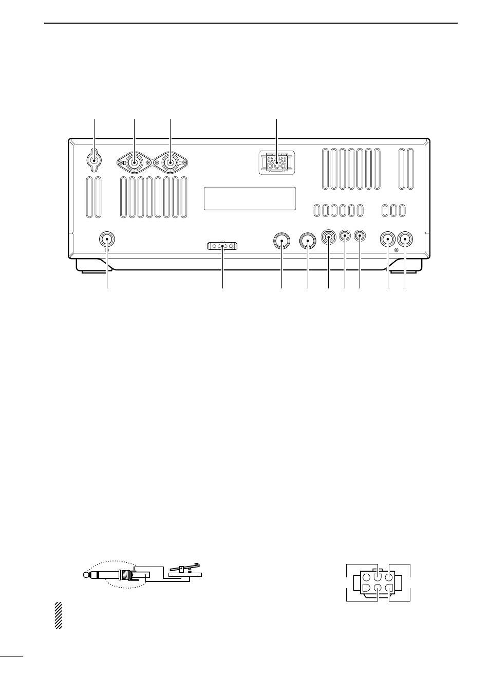
1
PANEL DESCRIPTION
■
Rear panel
q
o
!0
w
e
r
t y u
i
!3
!2
!1
Rear panel
view
+
_
(
+
)
(
_
)