Ds2100 user's manual (preliminary) – Moog DS2100 User Manual
Page 78
DS2100 User's Manual (Preliminary)
SECTION 3: WIRING AND INSTALLATION
PAGE 3-72
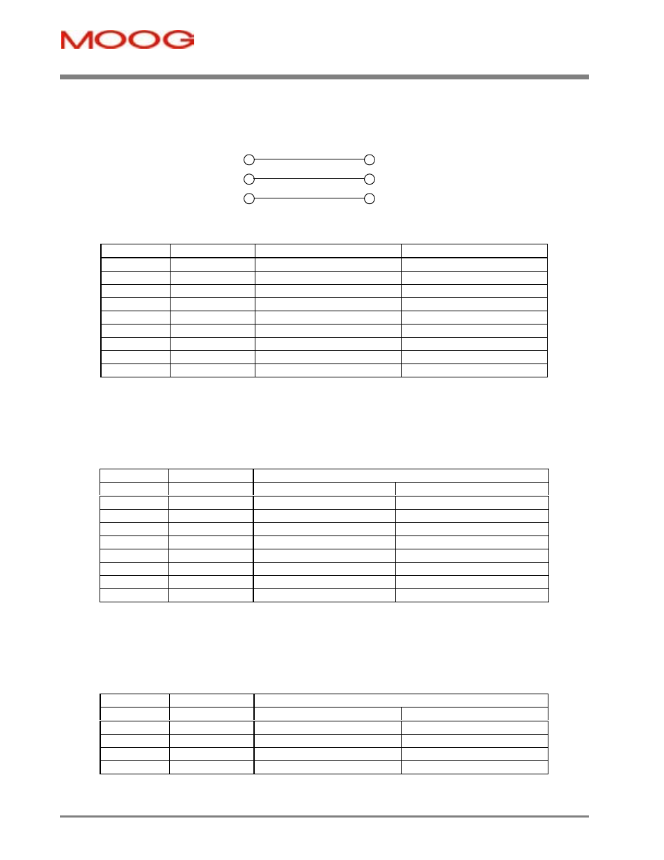
3.14.5.1 RS232
2
3
5
2
3
5
Rx
Tx
Gnd
Rx
Tx
PC
DS2100
-
Fixed connector: 9 pin, female Sub-D connector
-
Mating connector, 9 pin male Sub-D
-
Wiring: cable. 28-18AWG (0.14-0.82mm
2
)
Pos.
Name
Function
PC Signal
J1.1
-
connected to pin 4
DCD input
J1.2
TxD
Transmit Data
RxD input
J1.3
RxD
Receive Data
TxD output
J1.4
-
connected to pin 1 and 6
DTR output
J1.5
Gnd
Gnd
Gnd
J1.6
-
connected to pin 4
DSR input
J1.7
-
connected to pin 8
RTS output
J1.8
-
connected to pin 7
CTS input
J1.9
-
unused
RI input
3.14.5.2 Digital
Inputs
-
Fixed connector: 9 pins, male connector
-
Mating connector, 9 pins spring cage, female, supplied with the drive. Phoenix Contact (Part # FK-MC 0.5/9-ST-
2.5)
-
Wiring: cable. 28-20AWG (0.14-0.5mm
2
)
-
Wire stripping: 8 mm
Pos.
Name
Function
J2A.1
I1
Digital Input # 1
Drive Enable
J2A.2
I2
Digital Input # 2
User Configurable
J2A.3
I3
Digital Input # 3
User Configurable
J2A.4
I4
Digital Input # 4
User Configurable
J2A.5
I5
Digital Input # 5
User Configurable
J2A.6
I6
Digital Input # 6
User Configurable
J2A.7
I7
Digital Input # 7
User Configurable
J2A.8
I8
Digital Input # 8
User Configurable
J2A.9
RET
Digital Input Ground
3.14.5.3 Digital
Outputs
-
Fixed connector: 5 pins, male connector
-
Mating connector, 5 pins spring cage, female, supplied with the drive. Phoenix Contact (Part # FK-MC 0.5/5-ST-
2.5)
-
Wiring: cable. 28-20AWG (0.14-0.5mm
2
)
-
Wire stripping: 8 mm
Pos.
Name
Function
J2B.1
Ext 24V DC
+24V Digital Output Supply
J2B.2
O1
Digital Output #1
User Configurable
J2B.3
O2
Digital Output #2
User Configurable
J2B.4
O3
Digital Output #3
User Configurable
J2B.5
Ext 24V Ret
Digital Output Return