Errata sheet ds2100 user's manual (preliminary) – Moog DS2100 User Manual
Page 7
Errata Sheet
DS2100 User's Manual (Preliminary)
PAGE 7
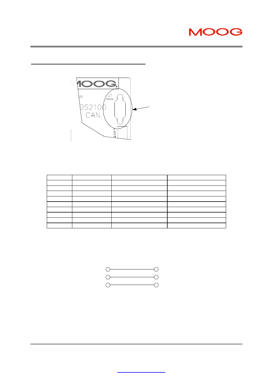
3.13.1
RS232 Serial Communications Interface
The pin assignment enables use of a 9-pin Sub-D cable with all signals connected straight through.
Serial Communications
Connector (RS232)
Figure 3.45 RS232 Connector Location
-
Fixed connector: 9 pin, female Sub-D connector
-
Mating connector, 9 pin male Sub-D
-
Wiring: cable. 28-18AWG (0.14-0.82mm
2
)
Pos.
DS2100 Signal
Function
PC Signal
J1.1
-
connected to pin 4
DCD input
J1.2
TxD
Transmit Data
RxD input
J1.3
RxD
Receive Data
TxD output
J1.4
-
connected to pin 1 and 6
DTR output
J1.5
Gnd
Gnd
Gnd
J1.6
-
connected to pin 4
DSR input
J1.7
-
connected to pin 8
RTS output
J1.8
-
connected to pin 7
CTS input
J1.9
-
unused
RI input
Table 3.29 J1, DS2100 RS232 Serial Interface Connector
2
3
5
2
3
5
Rx
Tx
Gnd
Rx
Tx
PC
DS2100
Figure 3.46 DS2100's J1 RS232 Wire Pin-out
The RS232 Cable shield should be connected to the metal body of the D-Type connector.
PDF created with pdfFactory Pro trial version