Ds2100 user's manual (preliminary) – Moog DS2100 User Manual
Page 71
SECTION 3: WIRING AND INSTALLATION
DS2100 User's Manual (Preliminary)
PAGE 3-65
-
Fixed connector: 9 pin, male & female Sub-D connector
-
Mating connector, 9 pin male & female Sub-D
-
Wiring: cable. 28-18AWG (0.14-0.82mm
2
)
Pos (x=A,B)
Signal
Description
J3x.1
-
not connected
J3x.2
CAN_L
CAN_L bus line (dominant low)
J3x.3
CAN_GND
CAN Ground
J3x.4
-
not connected
J3x.5
CAN_SHLD
Chassis Ground
J3x.6
CAN_GND
CAN Ground
J3x.7
CAN_H
CAN_H bus line (dominant high)
J3x.8
-
not connected
J3x.9
-
Optional CAN external positive supply, not connected.
Table 3.30 CAN Connector Pin Description
Note:-
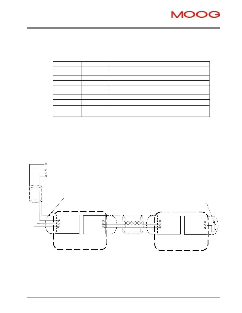
· CAN lines must be terminated in a 120Ohm resistance, between the positive and negative terminals (CAN-High and
CAN-Low) at both ends of the CAN network for correct operation.
· All pins of J3A and J3B are wired straight through the connectors of the DS2100.
User's PE
GND
CAN_L
CAN_H
Connect Cable Shields to
Metallic D-Sub Shell
Terminate CAN lines in
D-Shell with 120Ohms
at both ends of network
Connector J3A
DS2100
Connector J3B
7 CAN_H
2 CAN_L
3 CAN_GND
CAN_H 7
CAN_L 2
CAN_GND 3
Connector J3A
DS2100
Connector J3B
7 CAN_H
2 CAN_L
3 CAN_GND
CAN_H 7
CAN_L 2
CAN_GND 3
Figure 3.48 DS2100 CAN Wiring and Termination