Ds2100 user's manual (preliminary) – Moog DS2100 User Manual
Page 67
SECTION 3: WIRING AND INSTALLATION
DS2100 User's Manual (Preliminary)
PAGE 3-61
3.12.2.1
Drive Ready Relay
The DS2100 provides 1 relay outputs on connector J2C. This relay closes when the drive is ready and no faults are
present.
-
Fixed connector: 2 pins, male connector
-
Mating connector, 2 pins spring cage, female, supplied with the drive. Phoenix Contact (Part # FK-MC 0.5/2-ST-
2.5)
-
Wiring: cable. 28-20AWG (0.14-0.5mm
2
)
-
Wire stripping: 8 mm
Pos.
Name
Function
J2C.1
Drive Ready 1
Drive ready relay contact pin 1 Drive Ready Relay Contact
J2C.2
Drive Ready 2
Drive ready relay contact pin 1 Drive Ready Relay Contact
Table 3.28 J2B, DS2100 Digital Output connector
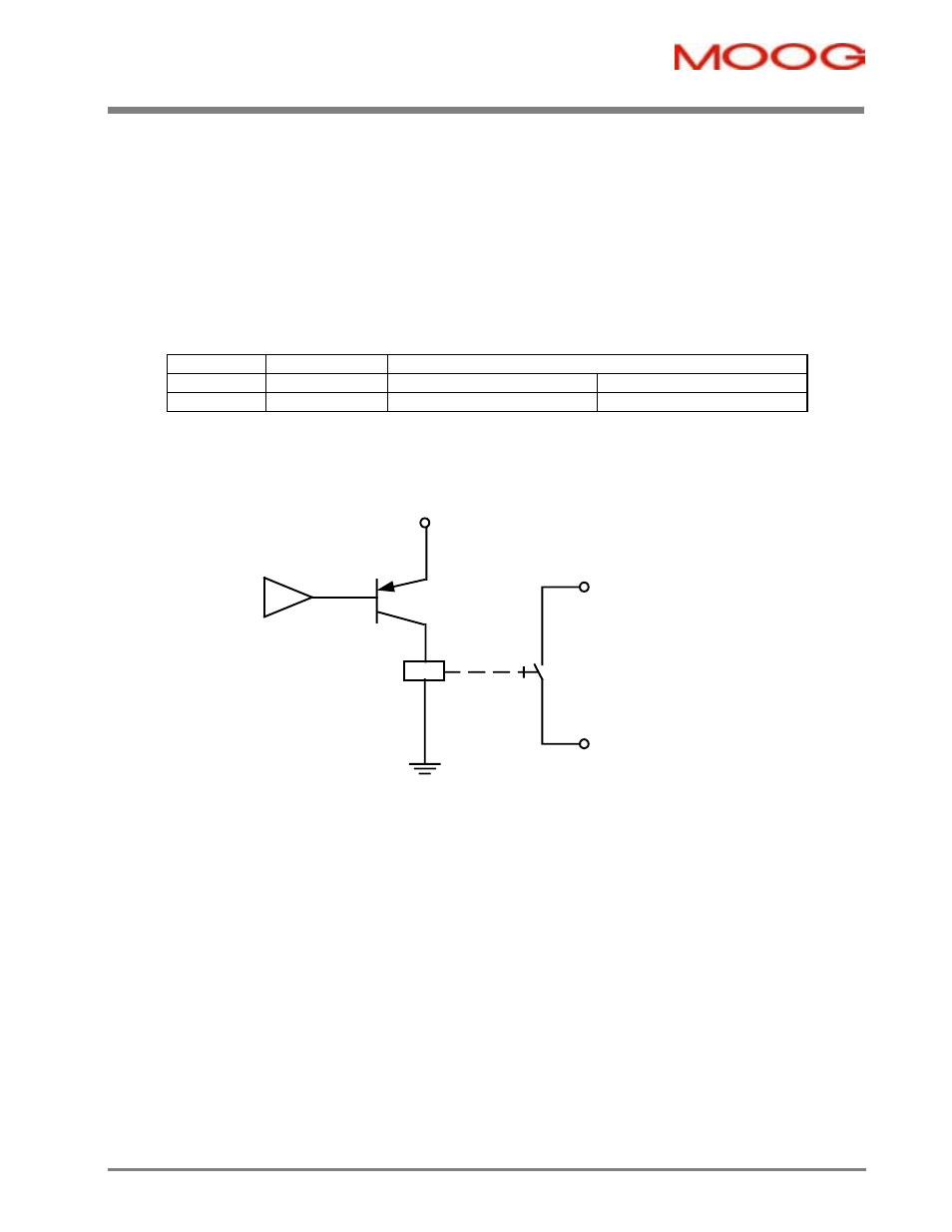
The following electrical description applies to the Drive ready relay of the DS2100.
J2C.1
Drive Ready 1
Drive Ready
Relay
J2C.2
Drive Ready 2
5V
Figure 3.43 Drive Ready Relay Output
Note that:-
§
Closed when drive ready and no faults.
§
Max. voltage 36 V
§
Max. contact current 100 mA