Ds2100 user's manual (preliminary), Errata, 5 motor encoder connection – Moog DS2100 User Manual
Page 5: Encoder connector
DS2100 User's Manual (Preliminary)
Errata
PAGE 4
3.11.5
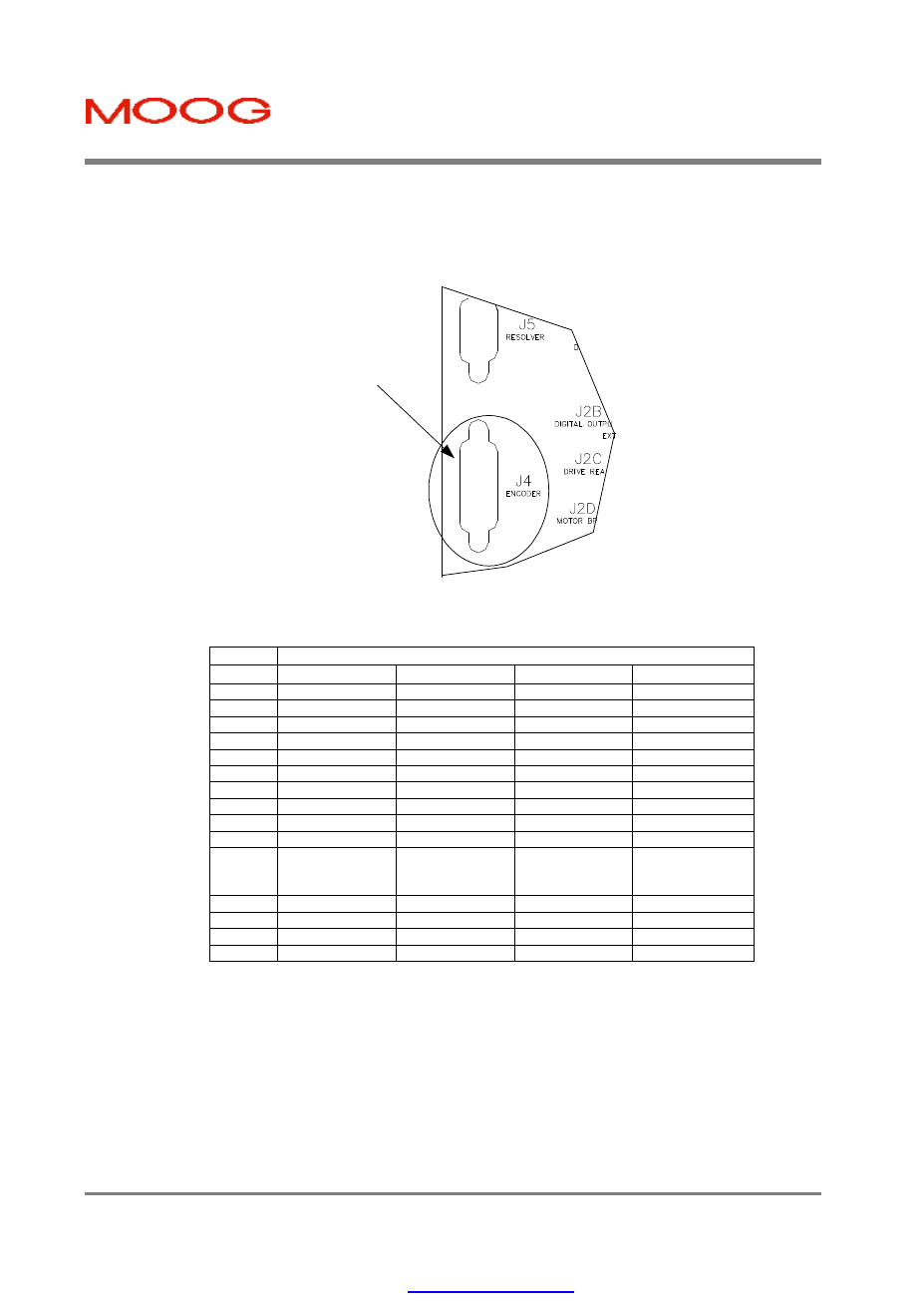
Motor Encoder Connection
The DS2100 encoder input supports a variety of encoders. These include Analogue, SSI, Hiperface and Endat. The
connections to the drive for each of these encoder types are given in Table 3.25.
Encoder
Connector
Figure 3.38 Motor Encoder Connector Location
-
Fixed connector: 15 pin, female Sub-D connector
-
Mating connector, 15pin male Sub-D
-
Wiring: cable. 28-18AWG (0.14-0.82mm
2
)
Encoder Type
Pos
Analogue
SSI
Hiperface
Endat
J4.1
Shield
Shield
Shield
Shield
J4.2
- Sine
-
- Sine
- Channel B
J4.3
- Cosine
-
- Cosine
- Channel A
J4.4
Gnd Supply
Gnd Supply
Gnd Supply
Gnd Supply
J4.5
-
- Clock
-
- Clock
J4.6
- Channel Z (Zero)
- Data
RS485 -
- Data
J4.7
-
-
-
-
J4.8
NTC/PTC
NTC/PTC
NTC/PTC
NTC/PTC
J4.9
+ Sine
-
+ Sine
+ Channel B
J4.10
+ Cosine
-
+ Cosine
+ Channel A
J4.11
+5 V .. +12V
Supply (150 mA
max.)
+5 V .. +12V
Supply (150 mA
max.)
+5 V .. +12V
Supply (150 mA
max.)
+5 V .. +12V
Supply (150 mA
max.)
J4.12
- Fault
+ Clock
-
+ Clock
J4.13
+ Channel Z (Zero)
+ Data
RS485 +
+ Data
J4.14
Gnd Supply
Gnd Supply
Gnd Supply
Gnd Supply
J4.15
NTC/PTC
NTC/PTC
NTC/PTC
NTC/PTC
Table 3.25 Encoder Cable Input Connections
PDF created with pdfFactory Pro trial version