Paralleling through the dc bus, Ds2100 user's manual (preliminary), 1 m a size dc bus inter-connection – Moog DS2100 User Manual
Page 40
DS2100 User's Manual (Preliminary)
SECTION 3: WIRING AND INSTALLATION
PAGE 3-34
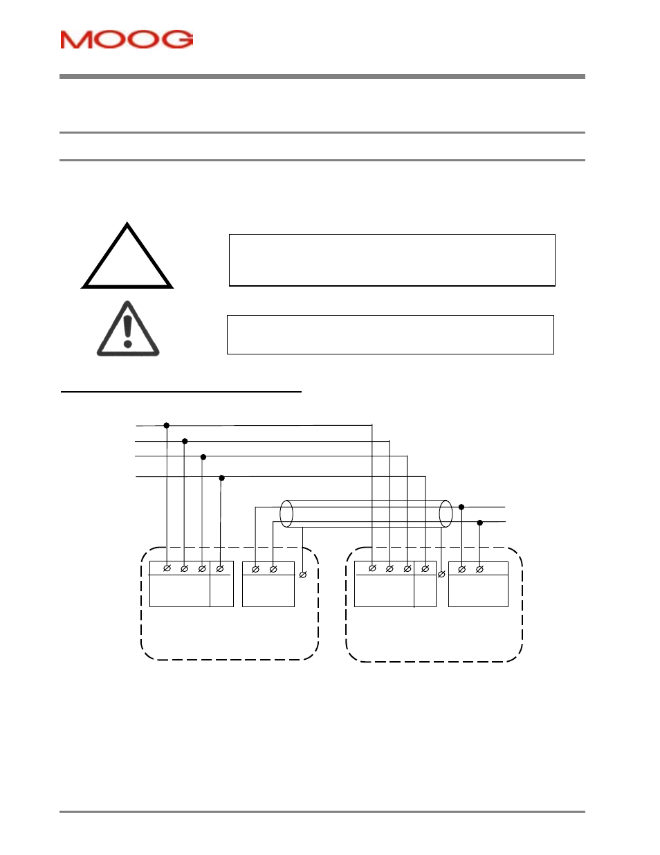
3.9 Paralleling DS2100 Units through the D.C. Bus
DS2100 units can be paralleled via the D.C. Bus, in order to share regeneration power.
3.9.1
mA Size DC Bus Inter-connection
Tie screen to chassis via
EMC bracket. See Section 2
L1 L2 L3 PE
(J6.4)(J6.5)(J6.6) Stud
Connector J6
DC- DC+
(J6.1)(J6.2)
DS2100 mA
L1 L2 L3 PE
(J6.4)(J6.5)(J6.6) Stud
DC- DC+
(J6.1) (J6.2)
DS2100 mA
a.c. Mains
L1
L2
L3
Protective
Earth
Connector J6
Figure 3.21 Size
mA DC Bus Inter-connection
-
Fixed connector: 12 pins, male connector
-
Mating connector, 12 pins, female, supplied with the drive. Phoenix Combicon (Part # GMSTB 2.5/12-ST-7.62)
-
mA size wiring: cable 14 AWG (2.1 mm
2
). Wire stripping: 7 mm.
-
PE Stud wiring: cable 6 AWG (13mm
2
)
-
Tightening torque: 0.5Nm.
To comply with the EMC Directive, the DC Bus cable must be
shielded and the shield must be connected to the housing with a 360
o
connection at both ends.
Required for
CE-Compliance
CAUTION – To connect drives through the DC bus, please contact
Moog application engineering for advice.