Ds2100 user's manual (preliminary), 2 can cable wiring, Can connectors – Moog DS2100 User Manual
Page 70
DS2100 User's Manual (Preliminary)
SECTION 3: WIRING AND INSTALLATION
PAGE 3-64
2
3
5
2
3
5
Rx
Tx
Gnd
Rx
Tx
PC
DS2100
Figure 3.46 DS2100's J1 RS232 Wire Pin-out
The RS232 Cable shield should be connected to the metal body of the D-Type connector.
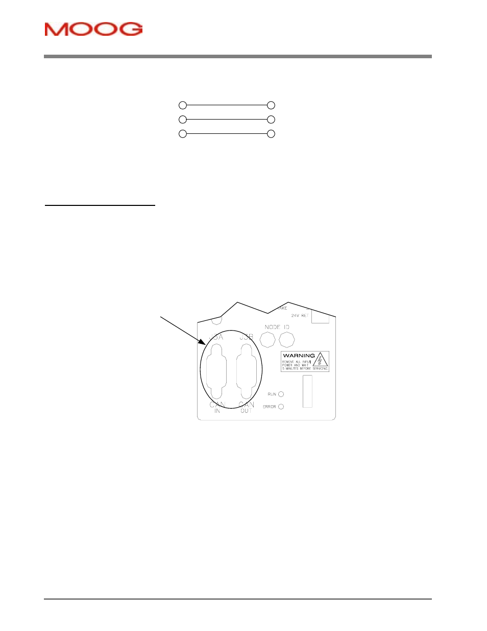
3.13.2 CAN Cable Wiring
The CAN-In and CAN-Out ports at J3A and J3B of the DS2100 provide the means to daisy-chain the CAN cabling
between DS2100 units and system controller. The CAN interface is equipped with driver and receiver for 24V systems.
These are optically isolated from the internal drive electronics for noise immunity. Internal supply of the isolated side
of the CAN is provided. No user supplied voltage is required. Two daisy chained 9-way D-Sub connectors, one male,
one female are also provided for ease of wiring.
Please refer to CAN Draft Standard 303, ‘Cabling and Connector Pin Assignment’ for further details of the CAN cabling
requirements.
CAN
Connectors
Figure 3.47 CAN Connector Location