Ds2100 user's manual (preliminary) – Moog DS2100 User Manual
Page 51
SECTION 3: WIRING AND INSTALLATION
DS2100 User's Manual (Preliminary)
PAGE 3-45
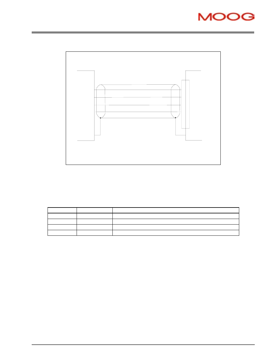
3.11.2.2 Size
A,
B
PE
GND (J6.7)
Motor
U (J6.10)
V (J6.9)
grounding of shield
via connector clamp
W (J6.8)
V
W
U
grounding of shield
via connector clamp
(or RF connection to
ground screw in
case of terminal board)
J6
DS2100 A, B
Figure 3.30 DS2100 A, B Motor Power Connection
-
Fixed connector: 10 pins, male connector
-
Mating connector, 10 pins, female, supplied with the drive. Phoenix Contact (Part # PC4 HV/10-ST-7.62)
-
A size wiring: cable 14AWG (2.1 mm
2
). Wire stripping: 7 mm
-
B size wiring: cable 12AWG (3.3 mm
2
). Wire stripping: 7 mm
-
Tightening torque: 0.5Nm.
Pos.
Name
Function
J6.7
GND
Motor Protective Earth
J6.8
W
Motor Phase W
J6.9
V
Motor Phase V
J6.10
U
Motor Phase U
Table 3.19 J6, Motor connector, A,B Size