Cabling procedure for mvpfx2-4/8 – Multi-Tech Systems MVPFX2-2 User Manual
Page 52
Mechanical Installation & Cabling
MultiVOIP FX User Guide
52
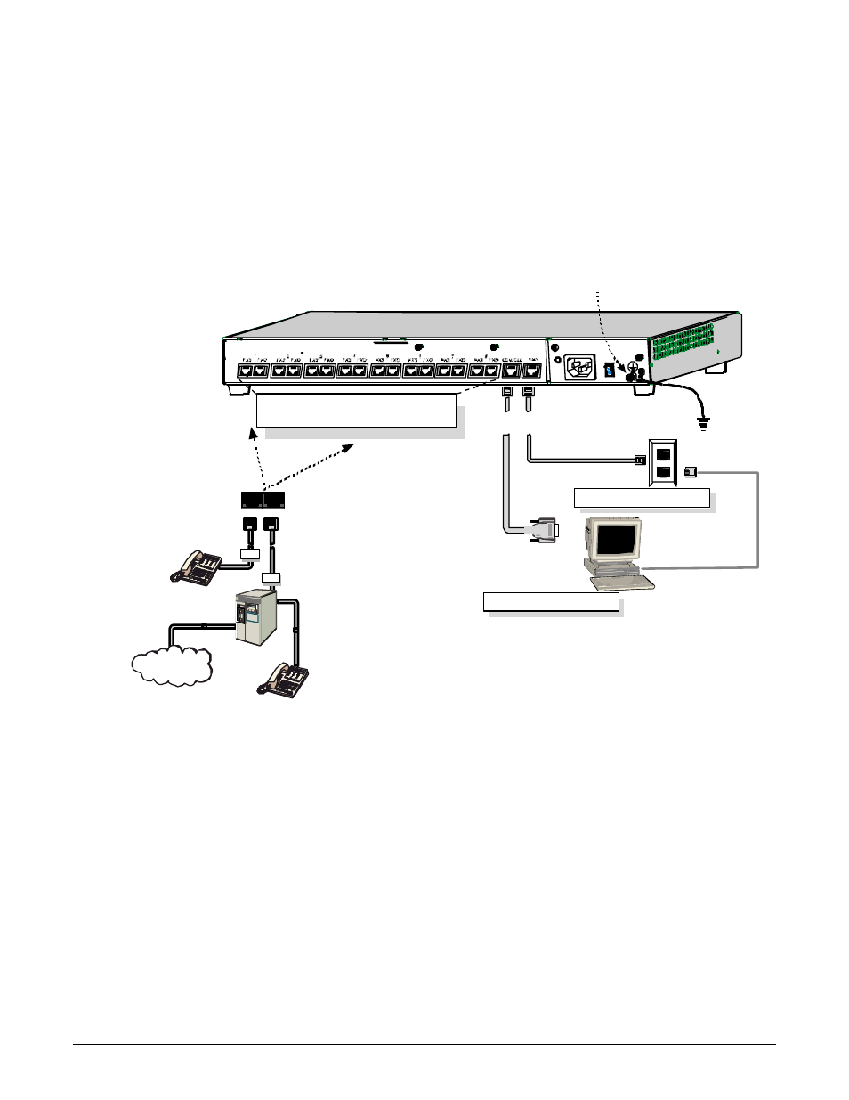
Cabling Procedure for MVPFX2-4/8
Cabling involves connecting the MultiVOIP to your LAN and telephone equipment.
1. Connect the power cord supplied with your MultiVOIP to a live AC outlet and to the power connector on
the back of the MultiVOIP as shown at top right in Figure 3-6.
Console Port Connection
Voice/Fax Channel Connections
Channels 1-4 Left-Most; for MVPFX2-4/8
Channels 5-8 Right-Most; for MVPFX2-8 only
FXS FXO
FXS
PSTN
FXO
RJ-11
Connectors
RJ-45
Connectors
Grounding
Screw
Groun ding
Cable
DB-9 Connector to
Computer Serial Port
for Console Functions
WAN/Ethernet Connection
VOIP Control
through
Web GUI
Figure 3-6: Cabling for MVPFX-4/8
2. Connect the MultiVOIP to a PC by using an RF-45 (male) to DB-9 (female) cable. Plug the RJ-45 end of the
cable into the Console port of the MultiVOIP and the other end into the PC serial port. See Figure 3-6.
3. Connect a network cable to the WAN 10/100 connector on the back of the MultiVOIP. Connect the other
end of the cable to your network switch.
4. For an FXS connection: Examples - analog phone, fax machine,
Key Telephone System
Connect one end of an RJ-11 phone cord to the Channel 1 FXS connector on the
back of the MultiVOIP. Connect the other end to the device.
For an or FXO connection: Examples - PBX extension, POTS line from telco central office
Connect one end of an RJ-11 phone cord to the Channel 1 FXO connector on
the back of the MultiVOIP. Connect the other end to the phone jack.