Figure 8-3 – exploded mechanical drawing 3 -6 – Maxon Telecom SP210 User Manual
Page 56
Maxon SP200/210 Radio SP200/210
EXPLODED MECHANICAL DRAWINGS & PARTS LISTS
Issue 1.0
Page 8-6
03/01
37
772-428
Shield Can (VCO)
NSP T0.2
1
38
406-764-B
PCB VCO
21 x 18 x 0.8 FR4 1/1
1
39
416-096-A
PCB RF
99 x 53.3 x 1.0 FR4 2/S
1
40
422-930-0
Spring Coil
2
41
753-049
Terminal
BSBM Gold-Plat
3
42
906-542
Insulation Plate
Fiber T0.3
1
43
895-549
Terminal Gasket
Silicone Rubber
1
44
895-763
Ring Gasket
Silicone Rubber
1
895-753
Volume Control O Ring
1
895-754
Antenna Control O Ring
1
66
895-661
Cushion
10 x 2.5 x 1.0 T EVA Sponge
1
67
600-804
Plastic Screw (Mic)
M1.8 x 5
2
71
906-939
Double Sided Tape
For Battery 24 x 33 x T0.4
1
72
895-685
Cushion
1
73
895-660
Cushion
15 x 9 x 1.0T EVA Sponge
1
74
772-496
Shield
1
75
772-497
Shield
1
Table 8-2 - Parts List for Exploded Mechanical Drawing 2
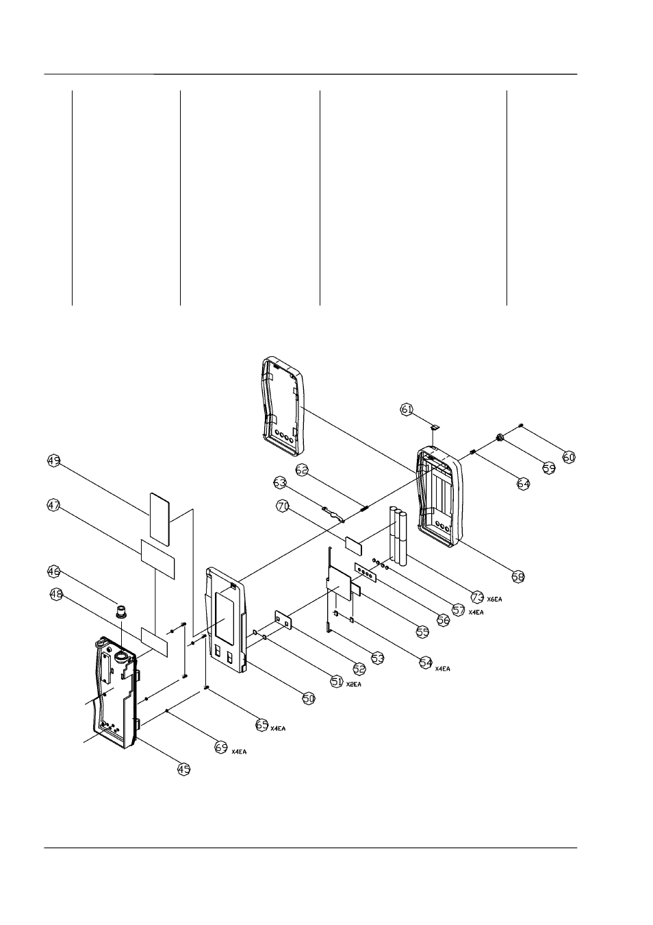
Figure 8-3 – Exploded Mechanical Drawing 3