Figure 8-2 - exploded mechanical drawing 2 -5 – Maxon Telecom SP210 User Manual
Page 55
SP200/210 Maxon SP200/210 Radio
Issue 1.0
EXPLODED MECHANICAL DRAWINGS & PARTS LISTS
03/01
Page 8-5
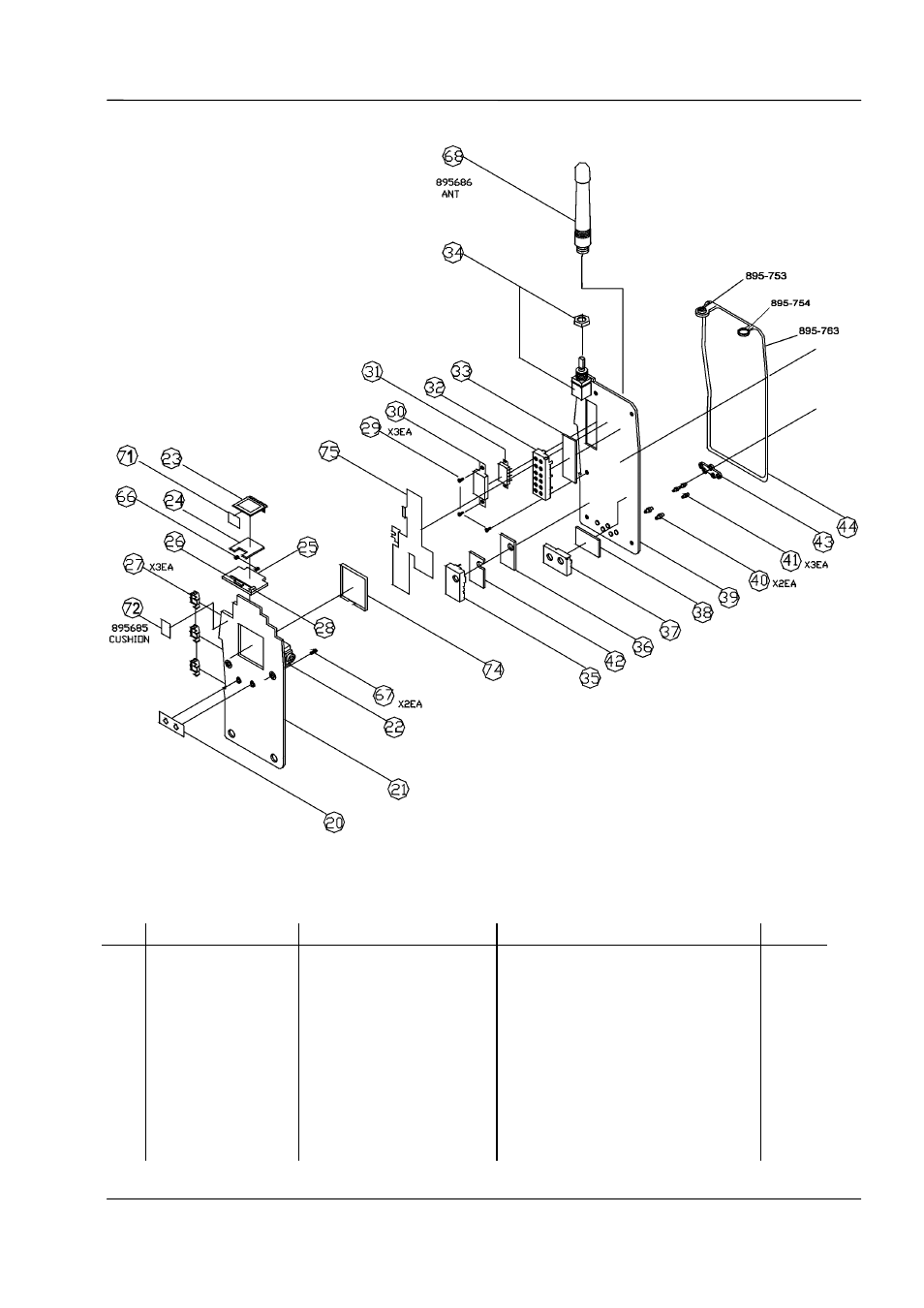
Figure 8-2 - Exploded Mechanical Drawing 2
No.
Part No.
Part Name
Description
Qty
25
406-767-A
PCB LCD
20.6 x 15 x 1.0 FR4 1/1
1
26
252-107-1
LED Display
SLE0022M
1
27
436-046-5
Sw TACT
SKPT-110VA
3
28
251-234-7
LED Chip
SML-020MLTT86 SMD
1
29
612-081
(+) Machine Screw (BH)
M2 x 4 ZN-Plat
3
30
772-462
Shield Can
NSP T0.2
1
31
221-324-6
Power Module
1
32
772-427
Shield Can (Front End)
NSP T0.2
1
33
406-787-A
PCB Front End
27 x 10 x 0.8 FR4 1/1
1
34
651-156
NUT
M7 BSBM
1
35
772-429
Shield Can (TCXO)
BSP T0.25 NI-PLAT
1
36
406-785-A
PCB TCXO
19 x 11 x 1.0 FR4 1/1
1