Table 5-98, Ctikp %qpvtqn 5wdrcig – Maxtor ATLAS 10K III User Manual
Page 146
SCSI Description
5-82
Maxtor Atlas 10K III
/CTIKP %QPVTQN 5WDRCIG
The Margin Control subpage (see Table 5-98) contains parameters that set and report
margin control values for usage between the initiator/target pair on subsequent
synchronous and paced transfers.
A MODE SELECT command will return the current settings for the initiator/target
pair. Fields that are not implemented will be reported as zero.
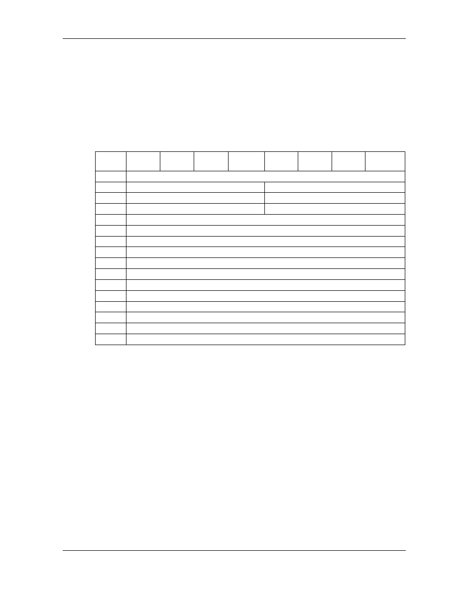
Table 5-98
Margin Control Subpage (01h)
The Driver Strength field indicates the relative amount of driver source currently used
by the driver. The Driver Strength field affects both the strong and week drivers. A
larger value indicates more driver source current.
The Driver Precompensation field indicates the relative difference between the weak
driver and the strong driver amplitudes when precompensation is enabled. A larger
value indicates a larger difference between the weak and strong amplitudes.
The Driver Asymmetry field indicates the relative difference between the amplitudes
of asserted and negated signals launched from the driver. A larger value indicates a
relatively stronger asserted signal compared to the negated signal.
The Driver Slew Rate field indicates the relative difference between the assertion and
negation magnitudes divided by the rise or fall time. A larger value indicates a faster
slew rate.
$KV
$[VG
0
Reserved
1
Driver Strength
Reserved
2
Drive’s Asymmetry
Driver Precompensation
3
Drive’s Slew Rate
Reserved
4
Reserved
5
Reserved
6
Reserved
7
Vendor Specific
8
Reserved
9
Reserved
10
Reserved
11
Reserved
12
Reserved
13
Reserved
14
Reserved
15
Reserved