Spring tension, Chip deflector positioning – Grizzly G1033X User Manual
Page 39
Model g1033X (Mfg. since 4/12)
-37-
Spring Tension
Tools Needed:
Qty
hex Wrench 6mm .............................................. 1
roller spring tension must be adjusted so that
feed roller pressure is uniform. roller spring ten-
sion will vary, depending on the type of wood you
plane. this is usually determined from trial-and-
error.
generally speaking, less spring tension is more
forgiving on workpieces. therefore, if you primar-
ily plane milled lumber with relatively consistent
surfaces, you can get away with having less
spring tension. likewise, if you primarily plane
rough lumber with inconsistent surface heights,
more spring tension is a must to keep the
workpiece feeding through the planer without
stopping.
if workpieces regularly stop feeding during opera-
tion, it may be a sign of weak spring tension.
To adjust feed roller spring tension:
1. locate the four adjustment screws located
on the top of the planer, as shown in
figure
36.
2. Adjust tension screws #1–#3 so that they
protrude
1
⁄
8
" above the head casting.
3. Adjust tension screw #4 so that it protrudes
5
⁄
16
" above the head casting.
figure 36. tension screw locations and
adjustments.
tension screws
#1 - #3 Adjust to
1
⁄
8
"
tension screw
#4 Adjust to
5
⁄
16
"
Chip Deflector
Positioning
Chip Deflector Gap Setting
if planer Used w/dust Collector ......................
1
⁄
4
''
if planer Used w/o dust Collector .................
1
⁄
16
''
Tools Needed:
Qty
Wrench or socket 10mm ................................... 1
hex Wrench 5mm .............................................. 1
the chip deflector keeps chips from falling onto
the outfeed roller.
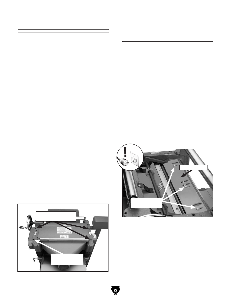
To adjust the deflector position:
1. disConnECt thE plAnEr FroM thE
poWEr soUrCE!
2. remove the dust port and top cover.
3. loosen the chip deflector mounting bolts
(see
figure 37).
Chip deflector
figure 37. Chip deflector and mounting bolts.
4. Make sure the deflector is beveled toward the
cutterhead. Move the deflector until the edge
is the correct distance (given above) from the
closest carbide insert. Use the cutterhead
pulley to rotate the cutterhead to ensure
clearance.
5. re-tighten the mounting bolts and return the
top cover to the planer.
Chip deflector
Mounting Bolts