Grizzly G1033X User Manual
Page 37
Model g1033X (Mfg. since 4/12)
-35-
6. place the rotacator under the right-hand
side of the infeed roller and find bottom
dead center on a serrated edge by sliding
the rotacator right to left in a zigzag pat-
tern—toward the infeed extension wing, then
toward the outfeed extension wing, and so
on.
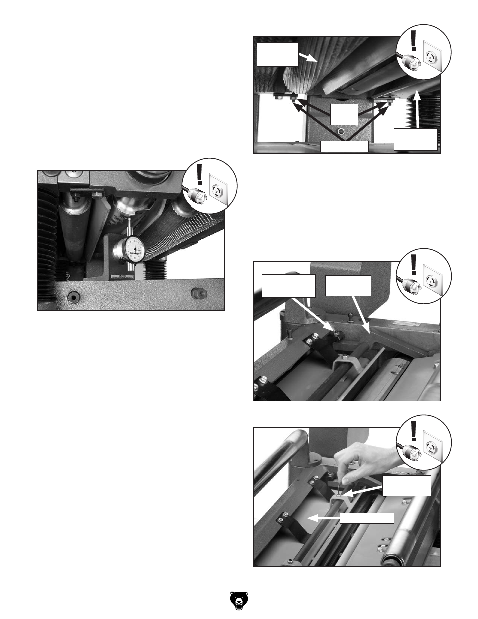
7. Adjust the height of the infeed roller on the
same side as the rotacator to the specifica-
tion given at the beginning of this procedure,
using the zero setting of the rotacator as a
reference point.
figure 32 shows the jam nut
and set screw for adjusting the roller height.
8. repeat Steps 6–7 on the left-hand side of the
infeed roller.
9. double-check and micro-adjust both sides
of the infeed roller, then carefully lock both
sides in place.
figure 31. Finding BdC with the rotacator.
figure 32. infeed and outfeed height adjustment
controls (one side shown).
figure 33. Adjusting pressure bar height.
figure 34. Adjusting chip breaker height.
10. Using the same zeroed reference on the
rotacator, adjust the height of the chip break-
er, pressure bar, and outfeed roller (
figure
32) to their given specifications. the adjust-
ment controls for each are shown in
figures
33 & 34.
Chip Breaker
pressure
Bar
Adjustment
location
Adjustment
location
Jam
nuts
set screws
outfeed
roller
infeed
roller
2. Make sure the cutters are set correctly.
3. lower the table at least 4" below the head
casting and lock the table in place.
4. remove the dust port, top cover, and belt
cover.
5. Using your rotacator, find BdC of any carbide
insert edge by slowly rocking the cutterhead
pulley back and forth, and set the rotacator
dial to zero, as shown in
figure 31.