Internal component heights – Grizzly G1033X User Manual
Page 36
-34-
Model g1033X (Mfg. since 4/12)
figure 29. table micro-adjustment screws.
7. repeat Steps 4–6 with each sprocket that
needs to be adjusted until the table-to-
cutterhead clearance is within 0.016" from
one side to the other.
8. Make sure the chain is properly fitted on the
sprockets, and tighten the idler sprocket and
lock bolts.
9. Micro-adjust the table position by loosening
the cap screws shown in
figure 29 and lifting
the table upward or downward until the table
and cutterhead are in alignment.
Note: This process may require adjusting the
columns on both the left and right hand sides
until you find the correct combination.
Internal Component
Heights
Distance below Cutter Edge at *bDC
infeed roller .............................................. 0.040"
Chip Breaker .............................................. 0.040"
pressure Bar .............................................. 0.040"
outfeed roller ........................................... 0.040"
Tools Needed:
Qty
hex Wrench 3mm .............................................. 1
hex Wrench 5mm .............................................. 1
Wrench or socket 10mm ................................... 1
rotacator (optional,
Page 26) ........................... 1
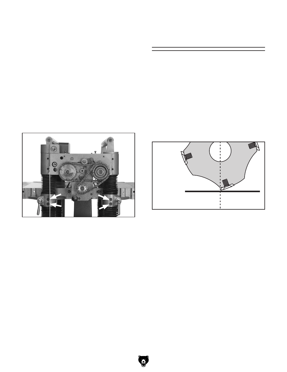
*BdC = Bottom dead Center (see
figure 30).
to ensure accurate results and make the adjust-
ment process quicker and easier, we recommend
using a rotacator (see
Page 26) for these adjust-
ments.
if a rotacator is not available, a 6' 2x4 cut into two
even sized pieces and a 0.40" feeler gauge can
be used, but care must be taken when jointing the
blocks to achieve accurate results.
To set the height of the infeed and outfeed
rollers, chip breaker, and pressure bar using
a Rotacator:
1. disConnECt thE plAnEr FroM thE
poWEr soUrCE!
figure 30. Carbide insert at bottom dead center
Ide9ZVY
8ZciZg
7diidb9ZVY
8ZciZg