5 interfaces, Interfaces – GE Industrial Solutions Digital Energy SNMP_WEB ADAPTER User Manual
Page 18
•
Connect the power to the box (left-most connector in the picture above). Make sure that the
SNMP/WEB Interface box is powered by the UPS output!
•
The UPS / Fail LED will switch OFF once the connection to the UPS is established.
If the LED remains continuously on, check the UPS connection and related cabling.
3.5 INTERFACES
UTP 10/100 – RJ45 port
Connection to an Ethernet 10/100 Mbits/s networks, using an UTP cable.
RS-232 – DB9 port
Serial communication, connection to a local console.
Use a straigth (1:1) serial cable for connection to a PC.
1
2
3
4
5
6
1
2
3
4
5
6
2
3
5
4
1
6
7
8
9
TD
RD
2
3
5
4
1
6
7
8
9
TD
RD
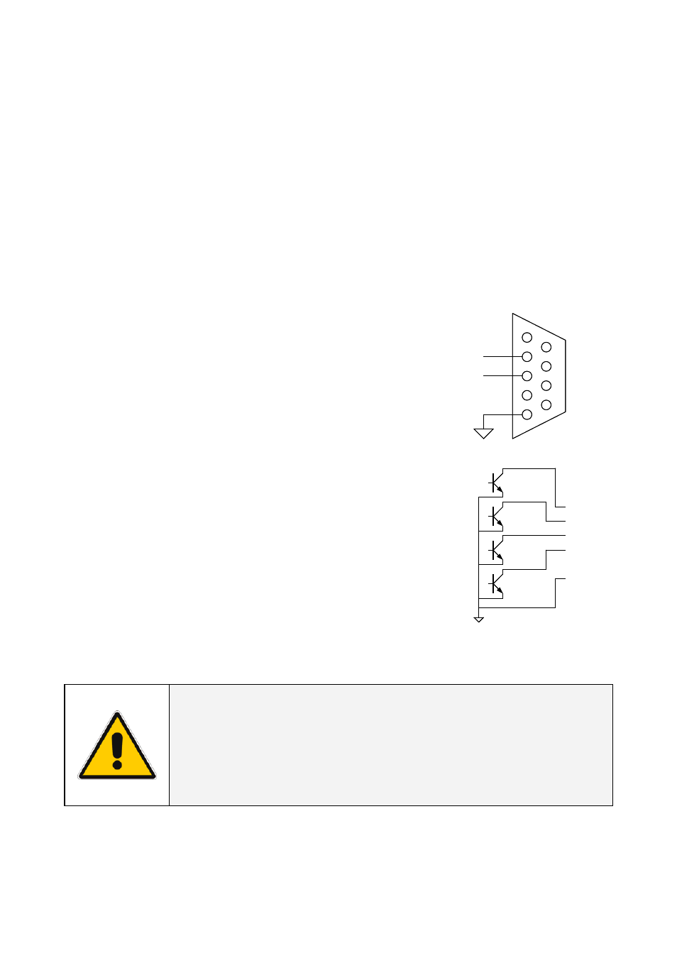
Connector pin-out as follows:
Pin #
Function
2
TD – Transmit Data
3
RD – Receive Data
5 GND
Contact interface – RJ11 port (1-ph plug-in version only)
Plug-in contact interface port.
Connector pin-out as follows:
Pin #
Function
1
Mains failure
2
General alarm *
3
Battery low
4
On bypass
5
N.C.
6
GND
(*) Active if the output voltage of the UPS is no longer guaranteed due to other circumstances than
already indicated by pin 1-3-4.
CAUTION !
The DB9 and RJ11 port share the same GND signal.
Exercise caution when both interfaces are used at the
same time, particularly when connecting these interfaces
to non-floating ground systems.
Modifications reserved
Page 18/24
ISG_CNT_SNM_BAS_CRD_1GB_V012.doc
Installation Guide SNMP/Web Adapter