7 servo control, 1 servo control circuit – FUJITSU MHW2120BS User Manual
Page 67
4.7 Servo Control
4.7 Servo Control
The actuator motor and the spindle motor are submitted to servo control. The
actuator motor is controlled for moving and positioning the head to the track
containing the desired data. To turn the disk at a constant velocity, the actuator
motor is controlled according to the servo data that is written on the data side
beforehand.
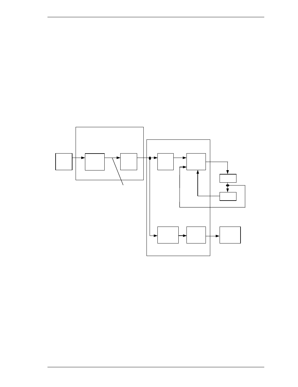
4.7.1 Servo control circuit
Figure 4.6 is the block diagram of the servo control circuit. The following
describes the functions of the blocks:
Head
Spindle
motor
CSR
VCM
Position Sense
VCM current
CSR: Current Sense Resister
VCM: Voice Coil Motor
(1)
MPU/HDC/RDC
(2)
Servo
burst
capture
(3)
DAC
(4)
SVC
Power
Amp
(5)
Spindle
motor
control
(6)
Driver
(7)
MPU
core
Figure 4.6 Block diagram of servo control circuit
C141-E249
4-13